Arrangement for detecting the angular position of a rotatable component

a technology of angular position and rotatable components, which is applied in the direction of instruments, measurement devices, magnitude/direction of magnetic fields, etc., can solve the problems of inability to use magnetically sensitive sensors, such as magnetoresistive sensors or vertical hall cells, which measure parallel to the sensor plane, and restrict the usable angular measurement rang

Active Publication Date: 2019-06-20
VITESCO TECH GERMANY GMBH
View PDF9 Cites 6 Cited by
  • Summary
  • Abstract
  • Description
  • Claims
  • Application Information

AI Technical Summary

Benefits of technology

[0023]In a further advantageous configuration of the arrangement disclosed herein, at least one of the magnetically sensitive elements is a vertical Hall cell. Further, at least one of the magnetically sensitive elements can be based on the magnetore

Problems solved by technology

However, the usable angular measuring range is restricted by the segmented multi-pole-pair magnet, and so it is only possible to capture a range of 360° divided by the number of p

Method used


Image

  • Arrangement for detecting the angular position of a rotatable component
  • Arrangement for detecting the angular position of a rotatable component

Examples


Embodiment Construction

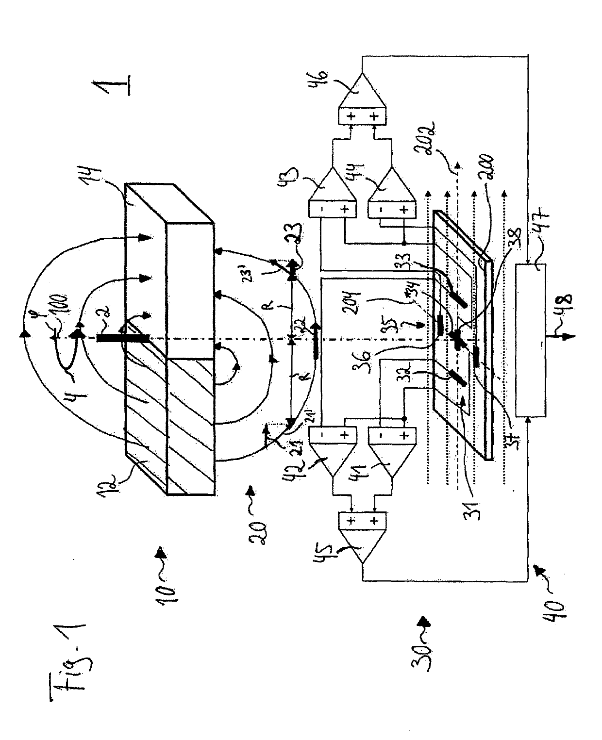
[0027]FIG. 1 shows an embodiment of an arrangement 1 according to the invention for capturing the angular position p of a component 2 that is rotatable about an axis of rotation 100. By way of example, the rotatable component 2 can be a shaft of a rotor of a DC motor. In further exemplary embodiments of the arrangement 1, the rotatable component 2 can be a throttle shaft of a throttle housing of a combustion engine or of an actuator for mechanical adjustment.

[0028]The arrangement 1 of FIG. 1 has a magnet 10, which produces a magnetic field 20. In FIG. 1, the magnetic field lines of the magnetic field 20 are plotted schematically. As illustrated in FIG. 1, the magnet 10 has two poles, namely a north pole 12 and a south pole 14. The magnet 10 is arranged in relation to the axis of rotation 100 such that the axis of rotation 100 extends centrally through the magnet 10, in particular through the interface between the north pole 12 and the south pole 14. The component 2 is rotatable abou...


PUM


Abstract

An arrangement for detecting the angular position of a rotatable component includes: a magnet, configured to generate a magnetic field, and a sensor assembly, configured to detect the magnetic field, and to supply therefrom an angle signal corresponding to the angular position of the component. The sensor assembly has a first sensor group, including a first magnetically sensitive element, a second magnetically sensitive element, and a third magnetically sensitive element, a second sensor group, having a fourth magnetically sensitive element, a fifth magnetically sensitive element, and a sixth magnetically sensitive element, and an evaluation unit, which is connected to each of the magnetically sensitive elements of the first sensor group and the magnetically sensitive elements of the second sensor group and supplies the angle signal corresponding to the angular position of the component.

Description

CROSS-REFERENCE TO RELATED APPLICATIONS[0001]This is a U.S. national stage of application No. PCT / EP2017 / 052057 filed on 31 Jan. 2017, which claims priority to the Germany Application No. 10 2016 202 378.0 filed 17 Feb. 2016, the content of both incorporated herein by reference.BACKGROUND OF THE INVENTION1. Field of the Invention[0002]The present invention relates to an arrangement (i.e., assembly) for capturing the angular position of a component that is rotatable about an axis of rotation.2. Related Art[0003]The use of magnet-based angle sensors for capturing the angular position of a component that is rotatable about an axis of rotation is known. By way of example GB 2 505 226 A discloses an arrangement, a method and a sensor for measuring an angular position using a multi-pole magnet with compensation of magnetic disturbance / interference fields. The arrangement disclosed therein has a multi-pole-pair magnet attached to a rotor and a stationary sensor. The sensor comprises a plur...

Claims


Application Information

Patent Timeline
IPC IPC(8): G01D5/14G01D5/244
CPCG01D5/145G01D5/24438G01D5/24471G01R33/06
Inventor WALLRAFEN, WERNER
Owner VITESCO TECH GERMANY GMBH
Why Eureka
Try Eureka