

Laser ultrasonic testing
a laser ultrasonic and testing technology, applied in the direction of ultrasonic/sonic/infrasonic wave generation, solids analysis using ultrasonic/ultrasonic/infrasonic wave, instruments, etc., can solve the problem of optical fiber cost being higher than cost, and achieve the effect of low-cost laser ultrasonic testing
- Summary
- Abstract
- Description
- Claims
- Application Information
AI Technical Summary
Benefits of technology
Problems solved by technology
Method used
Image

Examples
first embodiment
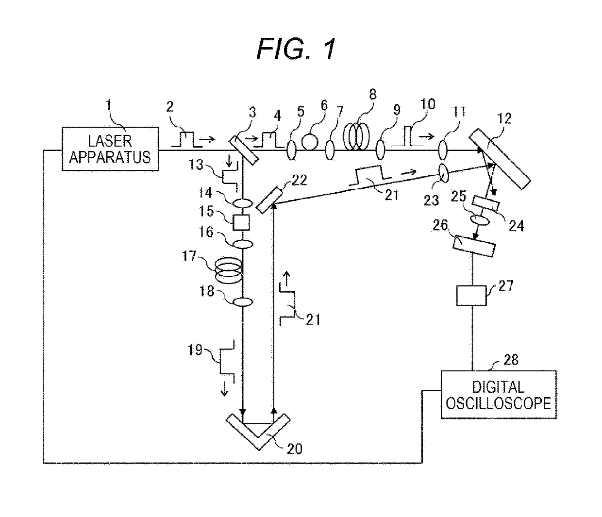
[0018]FIG. 1 is a configuration diagram illustrating laser ultrasonic testing according to a first example. Referring to FIG. 1, laser ultrasonic testing includes a laser apparatus 1 that generates a pulsed laser, a laser beam splitter 3 that splits a pulsed laser beam 2 output from the laser apparatus 1 into a first laser beam 4 and a second laser beam 13, a focus lens 5 that focuses the first laser beam 4 on a spectrum width expansion optical fiber 6, a focus lens 7 that focuses the laser beam output from the spectrum width expansion optical fiber 6 on a first pulse width conversion optical fiber 8, a collimator lens 9 that collimates the laser beam output from the first pulse width conversion optical fiber 8, and a focus lens 11 that focuses a collimated laser beam 10 on the surface of a test object 12. Further, the laser ultrasonic testing includes a focus lens 14 that focuses the second laser beam 13 split by the laser beam splitter 3 on a wavelength conversion crystal 15, a fo...
second embodiment
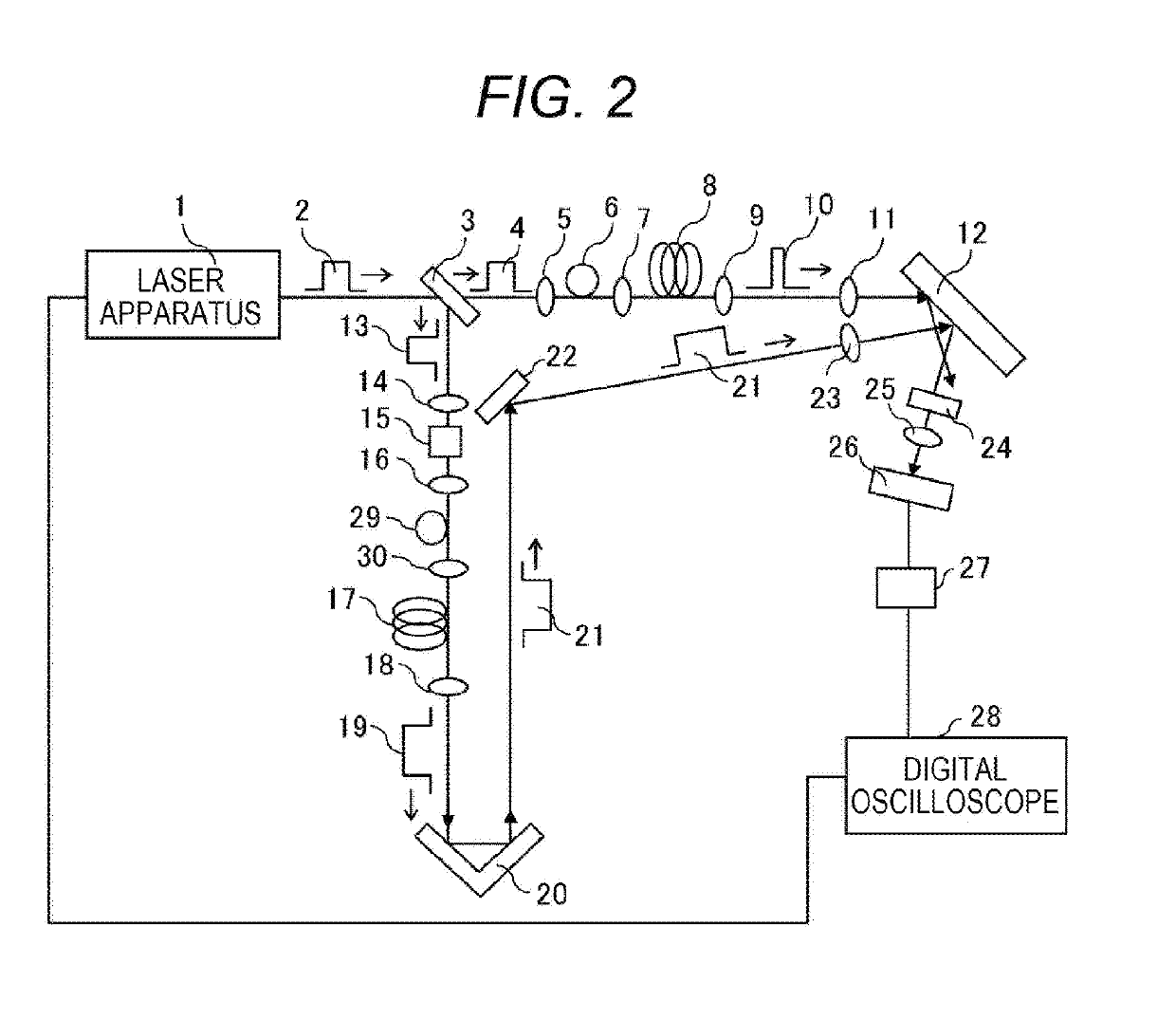
[0025]FIG. 2 is a configuration diagram illustrating laser ultrasonic testing according to a second embodiment. In FIG. 2, the same components as those illustrated in FIG. 1 are denoted by the same reference numerals, and descriptions thereof are omitted. FIG. 2 differs from FIG. 1 in that a spectrum width expansion optical fiber 29 and a focus lens 30 that condenses light on the second pulse width conversion optical fiber 17 are provided.
[0026]The spectrum width of the second pulse is expanded by the spectrum width expansion optical fiber 29 serving as a spectrum width expansion member, thereby making it possible to increase the expansion of the pulse width in the second pulse width conversion optical fiber 17. A high non-linear optical fiber or a photonic crystal fiber may be used as the spectrum width expansion optical fiber 29. By expanding the spectrum width from 1 nm to 100 nm by using the Super Continuum phenomenon described in the first embodiment, thereby making it possible...
third embodiment
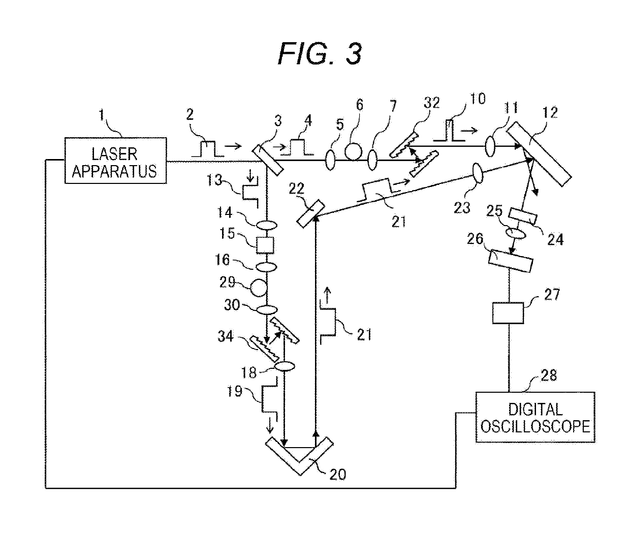
[0028]FIG. 3 is a configuration diagram illustrating laser ultrasonic testing according to a third embodiment. In FIG. 3, the same components as those illustrated in FIG. 2 are denoted by the same reference numerals, and descriptions thereof are omitted. FIG. 3 differs from FIG. 2 in that grating pairs 32 and 34 are used instead of the first pulse width conversion optical fiber 8 and the second pulse width conversion optical fiber 17, respectively.
[0029]By adjusting an interval between the grating pairs, the amount of dispersion necessary for pulse width compression or pulse width expansion can be adjusted.
[0030]While a set of grating pair is used in the third embodiment, a plurality of grating pairs may be used, or grating pairs may be used in combination with a pulse conversion optical fiber so as to obtain a desired amount of dispersion. Further, grating pairs may be applied to the configuration according to the first embodiment.
PUM
| Property | Measurement | Unit |
|---|---|---|
| wavelength | aaaaa | aaaaa |
| wavelength | aaaaa | aaaaa |
| wave length | aaaaa | aaaaa |
Abstract
Description
Claims
Application Information