Touch panel

a touch panel and touch technology, applied in the field of touch panels, can solve the problems of increasing the total thickness of the touch panel, relatively not easy to break the touch panel, and unfavorable display thinness and lightness, and achieves excellent inductive effect, large external force, and large induction signal.

Active Publication Date: 2019-06-20
AU OPTRONICS CORP
View PDF2 Cites 2 Cited by
  • Summary
  • Abstract
  • Description
  • Claims
  • Application Information

AI Technical Summary

Benefits of technology

[0003]The present invention relates to an embedded capacitive touch panel that uses thick glass (for example, glass having a thickness of more than 3 mm) as a cover lens. An area of each of first electrodes and an area of each of second electrodes in the touch panel have a ratio relationship. Because the thick cover lens in the disclosure can protect the touch panel, when an external force is applied to the touch panel, it is relatively not easy for the touch panel to be broken. In addition, because the area of each of the first electrodes and the area of each of the second electrodes in the touch panel (for example, a ratio of the area of each of the first electrodes to the area of each of the second electrodes ranges from 0.37 to 0.41) have a ratio relationship, a relatively large induction signal can be obtained according to the ratio relationship, and a problem that an induction signal is insufficient due to use of the thick glass can be solved. Therefore, the touch panel in the disclosure can withstand a relatively large external force and an inductive effect is also excellent.

Problems solved by technology

Therefore, the out-cell capacitive touch panel increases a total thickness of the touch panel, which is unfavorable for the display to be thin and light.
Because the thick cover lens in the disclosure can protect the touch panel, when an external force is applied to the touch panel, it is relatively not easy for the touch panel to be broken.

Method used


Image

  • Touch panel
  • Touch panel
  • Touch panel

Examples


Embodiment Construction

[0014]The present invention relates to an embedded capacitive touch panel that uses thick glass (for example, glass having a thickness of 3 to 5 mm) as a cover lens. When the touch panel is applied to a commercial display apparatus, even if an external force is applied to the touch panel for a long time, it is still relatively not easy for the touch panel to be broken. Therefore, the maintenance costs required due to destruction of an external force can be reduced. In addition, shapes of first electrodes and second electrodes and an area ratio of each of the first electrodes to each of the second electrodes in the touch panel in the disclosure are specially designed, so that the touch panel using thick glass can still have a good inductive effect.

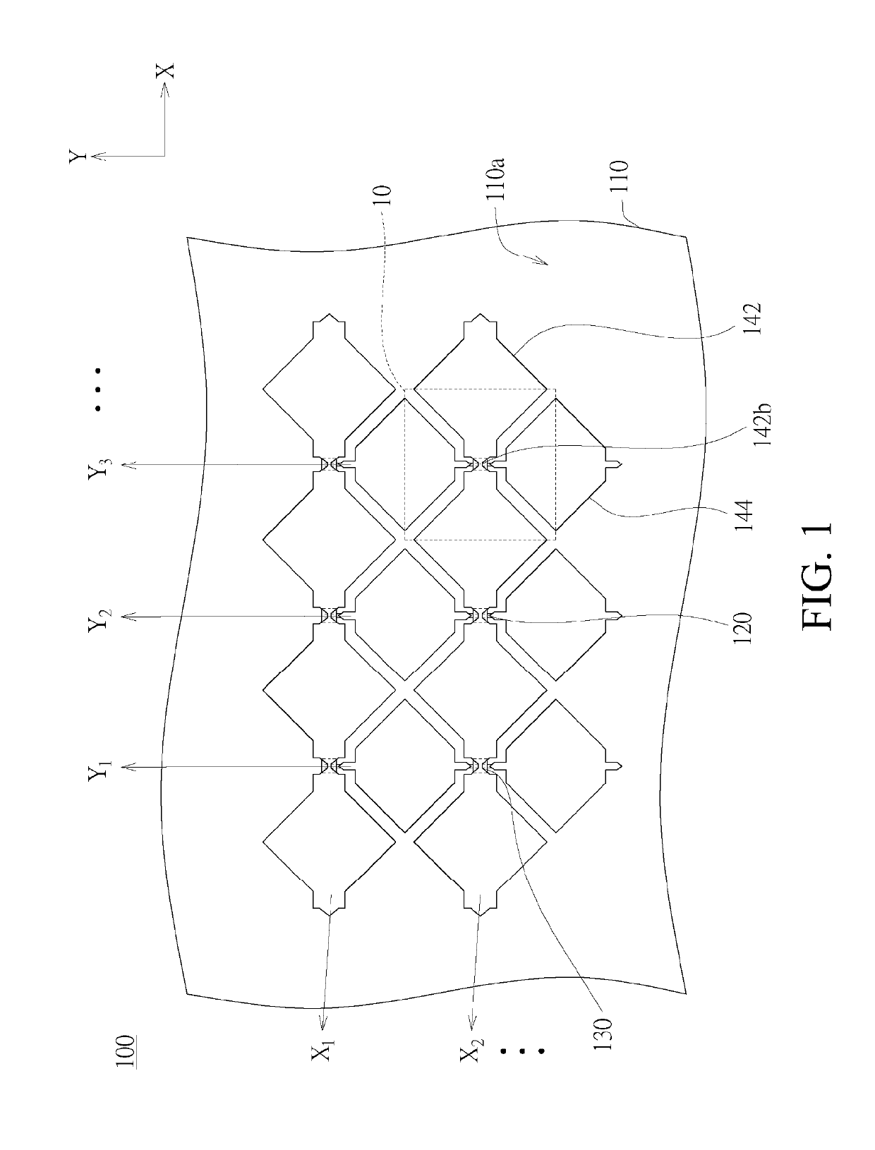
[0015]FIG. 1 is a top view of a touch panel 100 according to an embodiment of the disclosure.

[0016]Referring to FIG. 1, the touch panel 100 includes a substrate 110, a plurality of first electrode series X1, X2, . . . and a plurality of sec...


PUM


Abstract

A touch panel includes a substrate, a plurality of first electrode series, and a plurality of second electrode series. The substrate has a first surface. The first electrode series are disposed on the first surface. Each of the first electrode series extends along a first direction and includes a plurality of first electrodes. The second electrode series are disposed on the first surface. Each of the second electrode series extends along a second direction and includes a plurality of second electrodes.

Description

BACKGROUNDTechnical Field[0001]The present invention relates to a touch panel, and in particular, to an embedded capacitive touch panel.Related Art[0002]A current market has a large demand for touch panels. In the technologies of the touch panels, because a capacitive touch panel has advantages such as high reliability and a high reaction speed, the technology of the capacitive touch panel becomes the main development technology. A structure of the capacitive touch panel usually includes a liquid crystal display module (LCM) at a lower layer, a cover lens as a protection layer at an upper layer, and a transparent conductive layer sandwiched between a liquid crystal panel and the cover lens. According to a composition manner between the liquid crystal panel, the cover lens, and the transparent conductive layer, the capacitive touch panel is classified into an out-cell capacitive touch panel and an embedded capacitive touch panel. In the out-cell capacitive touch panel, a sensing elec...

Claims


Application Information

Patent Timeline
Patent Type & Authority Applications(United States)
IPC IPC(8): G06F3/041
CPCG06F3/0446G06F3/0448G06F3/0443G06F2203/04111G06F2203/04112G06F2203/04103G06F3/044G06F3/0412
Inventor CHEN, YA-TINGCHENG, SHENG-WEN
Owner AU OPTRONICS CORP
Why Eureka
Try Eureka