Power inductor

a technology of inductance and power, which is applied in the direction of inductance, transformer/inductance details, fixed inductance, etc., can solve the problems of insulation breakdown, deterioration of inductance, and material damage, so as to prevent inductance from being deteriorated, increase the content of polymer, and increase the specific resistance on the surface of the body

Active Publication Date: 2019-06-20
MODA INNOCHIPS CO LTD
View PDF0 Cites 8 Cited by
  • Summary
  • Abstract
  • Description
  • Claims
  • Application Information

AI Technical Summary

Benefits of technology

[0025]In the power inductor in accordance with the exemplary embodiments, the body may include the magnetic powder and the polymer, and the first thickness of the body disposed adjacent to the coil pattern may be formed by containing the magnetic powder having the lowest mean grain-size distribution. Thus, the insulation breakdown of the insulation layer disposed on the coil pattern may be prevented to prevent the inductance from being deteriorated.
[0026]Also, the predetermined second thickness from the uppermost and lowermost surfaces of the body may be formed by containing the magnetic powder having the lowest men grain-size distribution to increase the content of the polymer. Thus, the specific resistance on the surface of the body may increase, and thus, the delamination or peeling of the external electrode may be prevented to easily control the shape of the external electrode.
[0027]Also, the rest thickness between the first and second thicknesses may be formed by containing at least two magnetic powder having different mean grain-size distribution. Therefore, the magnetic permeability may be adjusted according to the size of the magnetic powder.
[0028]The thermal conductive filler may be further provided in the body to well release the heat of the body to the outside, thereby preventing the inductance from being deteriorated by the heating of the body. In addition, the insulation layer may be formed with a thin and uniform thickness on the coil pattern by using the parylene to improve the insulation between the body and the coil and reduce the deterioration in magnetic permeability due to the insulation layer.

Problems solved by technology

However, the magnetic material has a relatively low saturation magnetization value when compared to that of the metal material, and thus, the magnetic material may not realize high current properties that are required for the recent portable devices.
However, if the body is manufactured by using the metal, an eddy current loss and a hysteresis loss at a high frequency wave may increase to cause serious damage of the material.
However, the magnetic powder having a large size may cause insulation breakdown to deteriorate inductance.
That is, the magnetic power having the large size may pass through the insulation layer disposed on the coil pattern to come into contact with the coil pattern, thereby causing the insulation breakdown.
Thus, the inductance of the coil may be deteriorated.
Thus, there is a limitation that it is difficult to control a shape of an external electrode disposed on a surface of a body.

Method used


Image

  • Power inductor
  • Power inductor
  • Power inductor

Examples


embodiment and modified example

[0092]A power inductor in accordance with various embodiments and modified examples will be described.

[0093]FIG. 21 is a cross-sectional view of a power inductor in accordance with another exemplary embodiment.

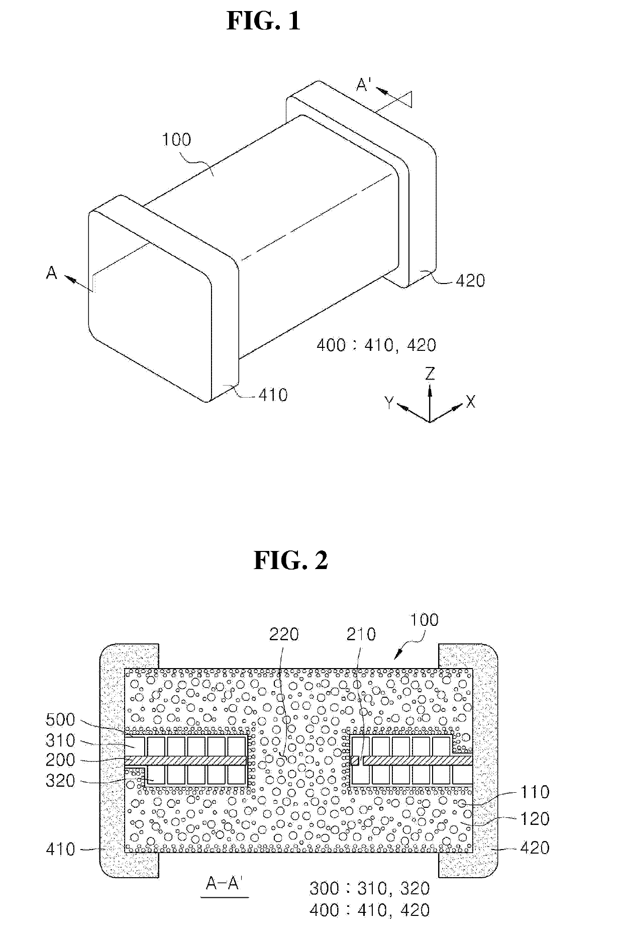
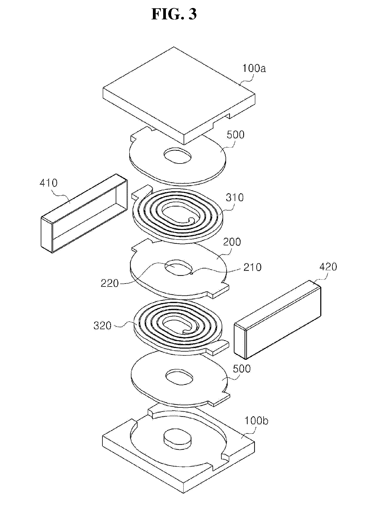
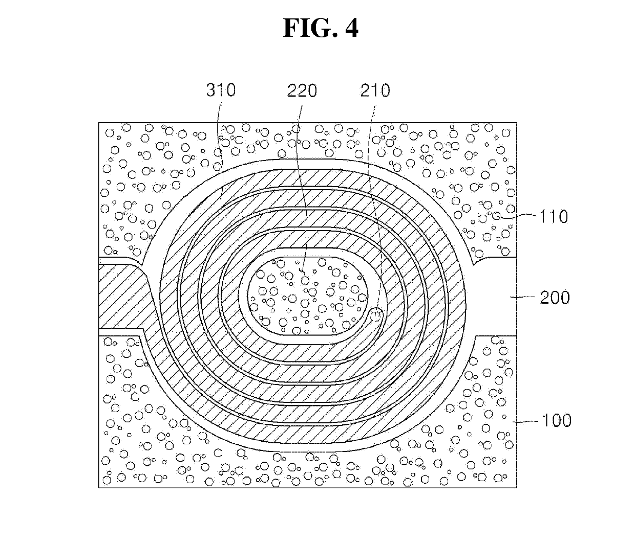
[0094]Referring to FIG. 21, a power inductor in accordance with another exemplary embodiment may include a body 100, a base 200 provided in the body 100, coil patterns 310 and 320 disposed on at least one surface of the base 200, external electrodes 410 and 420 provided outside the body 100, an insulation layer 500 provided on each of the coil patterns 310 and 320, and at least one magnetic layer 600 (610 and 620) provided in the body 100. That is, another exemplary embodiment may be realized by further providing the magnetic layer 600 in accordance with the foregoing embodiment. Hereinafter, constitutions different from those in accordance with the foregoing embodiment will be mainly described in accordance with another exemplary embodiment.

[0095]The magnetic layer 600 (610, ...


PUM

PropertyMeasurementUnit
mean particle diameteraaaaaaaaaa

Abstract

Provided is a power inductor. The power inductor includes a body including magnetic powder and a polymer, at least one base provided in the body and having at least one surface on which at least one coil pattern is disposed, and an insulation layer disposed between the coil pattern and the body. The body includes at least region in which the magnetic powder having a particle size different from that of the magnetic power in a remaining region is distributed.

Description

TECHNICAL FIELD[0001]The present disclosure relates a power inductor, and more particularly, to a power inductor having superior inductance properties and improved insulation.BACKGROUND[0002]A power inductor is mainly provided in a power circuit such as a DC-DC converter within a portable device. The power inductor is increasing in use instead of an existing wire wound choke coil as the power circuit is switched at a high frequency and is miniaturized. Also, the power inductor is being developed in the manner of miniaturization, high current, low resistance, and the like as the portable device is reduced in size and multi-functionalized.[0003]The power inductor according to the related art is manufactured in a shape in which a plurality of ferrites or ceramic sheets made of a dielectric having a low dielectric constant are laminated. Here, a coil pattern is formed on each of the ceramic sheets, and thus, the coil pattern formed on each of the ceramic sheets is connected to the ceram...

Claims


Application Information

Patent Timeline
Patent Type & Authority Applications(United States)
IPC IPC(8): H01F27/32H01F17/00H01F27/28
CPCH01F27/323H01F17/0013H01F27/2804H01F2027/2809H01F2003/106H01F2017/048H01F3/08H01F3/10H01F27/022H01F27/28
Inventor KIM, GYEONG TAENAM, KI JOUNGSEO, TAE GEUN
Owner MODA INNOCHIPS CO LTD
Why Eureka
Try Eureka