Display correction apparatus, program, and display correction system

a display and display technology, applied in the field of display correction apparatus, can solve the problems of difficult detection and classification, mura type defects, affecting the transmission of light through the display, etc., and achieve the effect of saving time and effor

Active Publication Date: 2019-06-20
SHARP KK
View PDF2 Cites 27 Cited by
  • Summary
  • Abstract
  • Description
  • Claims
  • Application Information

AI Technical Summary

Benefits of technology

[0034]According to the present invention, display correction based on an image captured using an image capture device can save time and effort such as moving a color-measurement device whenever necessary. In addition, display correction is performed using ambient-light-removed data, which is obtained by removing ambient light characteristics from a captured image of a display device. Thus, display correction is feasible even if a large portion is illuminated by ambient illumination.

Problems solved by technology

In the case of a liquid crystal display, however, mura type defects, which affect the transmission of light through the display or are generally objectionable to viewers, are generally caused by process flaws related to cell assembly.
The cyclical nature, randomness, and low contrast of such mura type defects make accurate detection and classification difficult, especially for liquid crystal displays.
With manufacturing variations in various components of a display, not all devices are capable of providing uniform display properties for the entire display area.
The process of manual visual identification tends to be inconsistent, and the identification heavily depends on the skills and expertise of the inspectors.
Also, different inspectors take a different amount of time to inspect a display, together with a limited number of skilled inspectors, which limits the inspection of mass produced displays.
In addition, inspectors tend to have variable inspection performance over time due to fatigue.
Unfortunately, color calibration tends to take a considerable amount of time and effort and is likely to fail.

Method used


Image

  • Display correction apparatus, program, and display correction system
  • Display correction apparatus, program, and display correction system
  • Display correction apparatus, program, and display correction system

Examples


Embodiment Construction

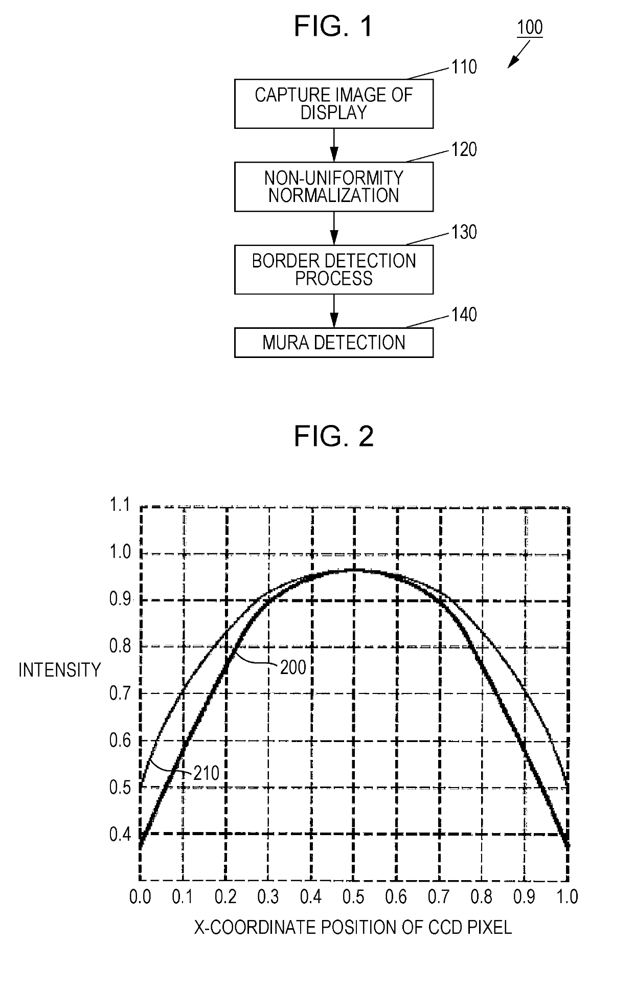
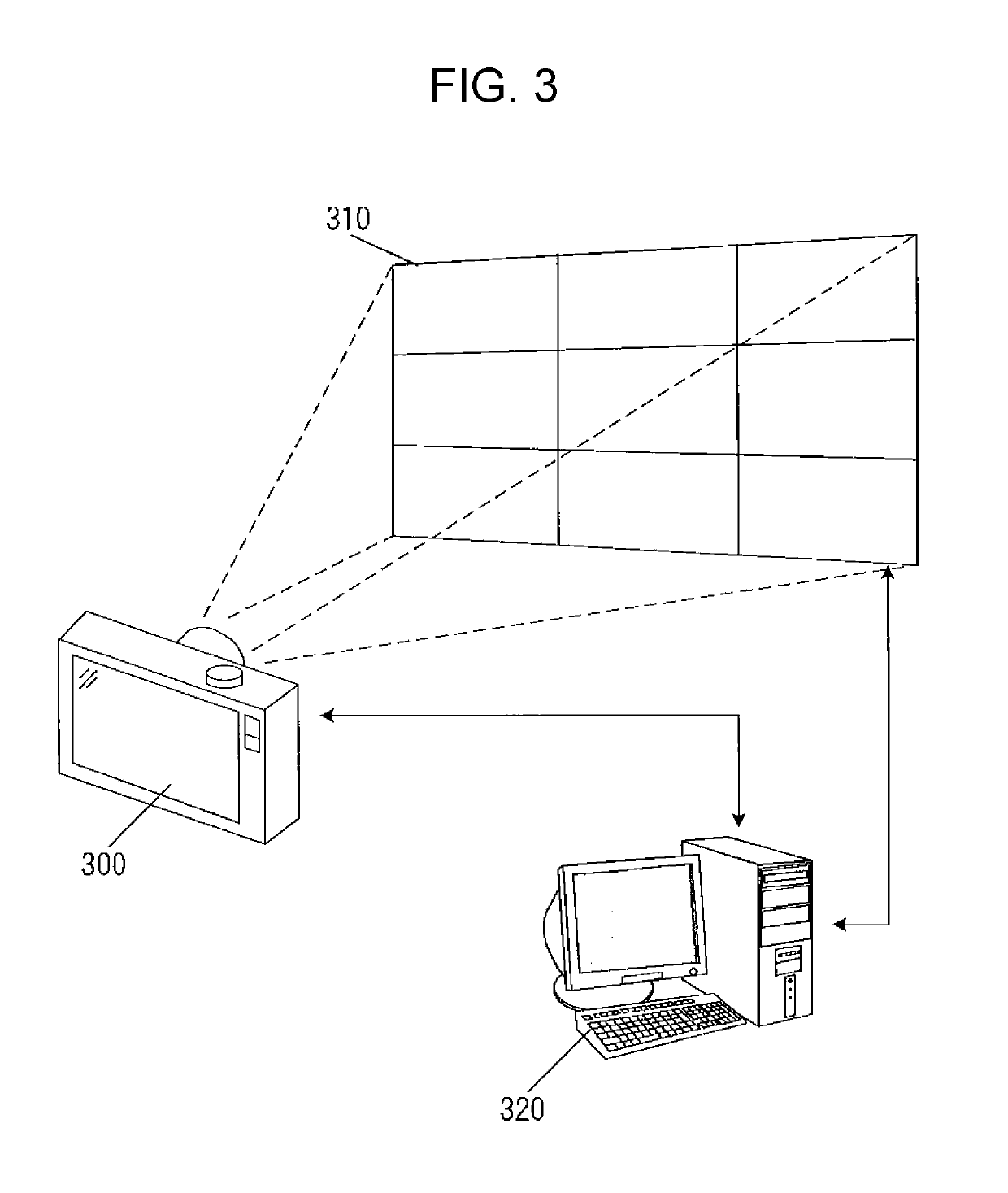
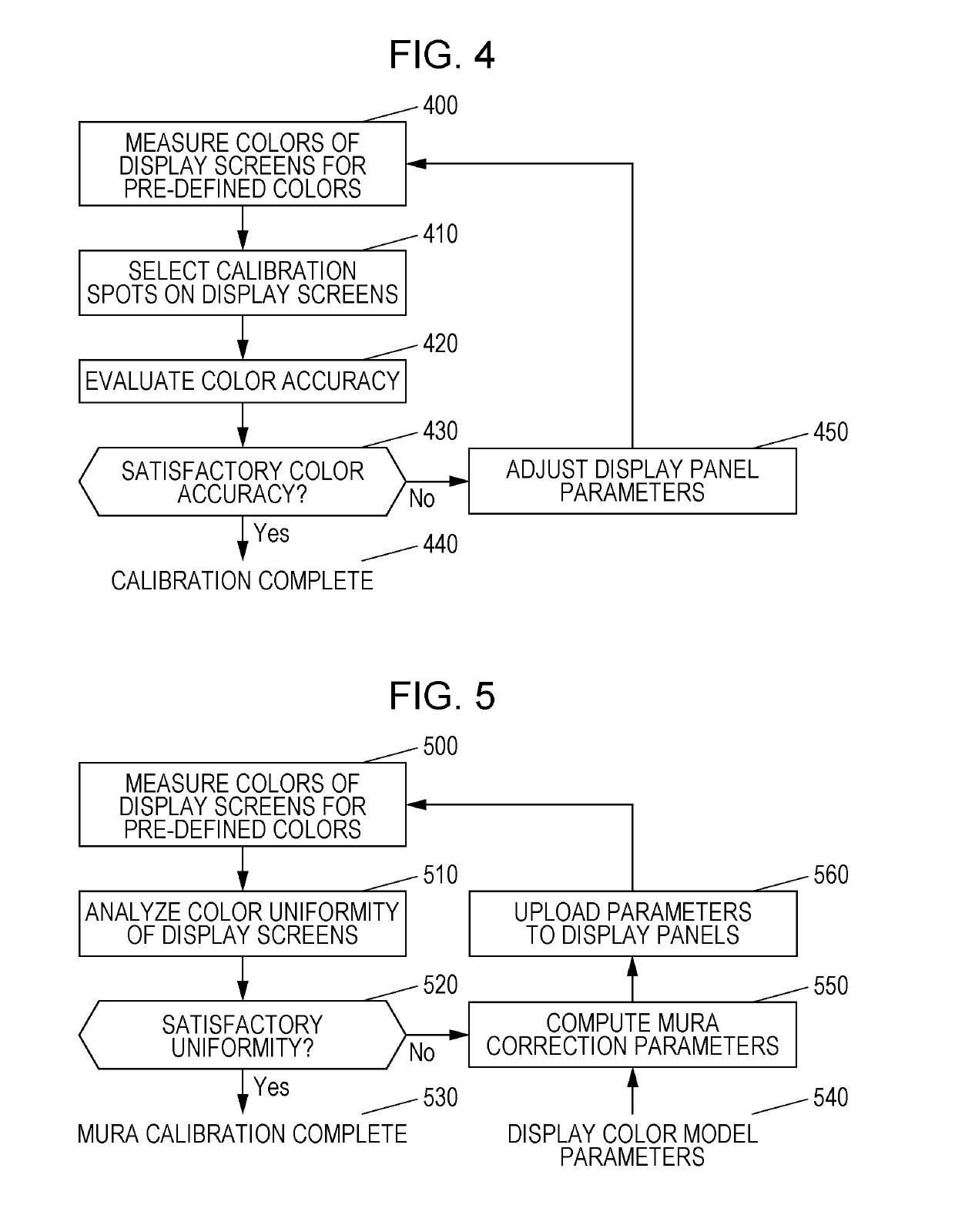
[0054]The following describes an embodiment of the present invention with reference to the drawings. In this embodiment, a display device refers to a flat panel display such as a liquid crystal display, a plasma display, or an organic EL display, and these displays are called display devices. Further, display correction refers to adjusting the characteristics of a display device to a known state or to, in multi-display settings, adjusting each of the display devices constituting a multi-display configuration so that the display devices have substantially the same appearance. The characteristics (display characteristics) of a display device are mainly optical characteristics based on the light output of the display device, such as the color temperature, luminance, grayscale value, and gamma value. Further, as a specific correction method implemented as display correction, mura correction for correcting display non-uniformity or color calibration for adjusting parameters of a display ...


PUM


Abstract

Display characteristics are calculated using a first captured image for determining ambient light characteristics and a second captured image including the ambient light characteristics and the display characteristics by removing the ambient light characteristics from the second captured image, and display correction is performed based on the display characteristics. This can provide a device that saves time and effort such as moving a color-measurement device when correcting the display characteristics of one or more display devices and that is able to perform display configuration even if a large portion is illuminated by ambient illumination.

Description

TECHNICAL FIELD[0001]The present invention relates to a display correction apparatus and the like for one or more displays.BACKGROUND ART[0002]Display devices typified by displays have been hitherto widely used to display presentations, display digital signage, and so on.[0003]Characteristics of display devices differ from device to device. Flat panel displays, such as a liquid crystal display, a plasma display, and an organic EL display, desirably display a uniform grayscale image when a uniform gray level input is provided. In the case of a liquid crystal display, however, mura type defects, which affect the transmission of light through the display or are generally objectionable to viewers, are generally caused by process flaws related to cell assembly. The cyclical nature, randomness, and low contrast of such mura type defects make accurate detection and classification difficult, especially for liquid crystal displays. With manufacturing variations in various components of a dis...

Claims


Application Information

Patent Timeline
Patent Type & Authority Applications(United States)
IPC IPC(8): H04N17/04
CPCH04N17/04G09G3/20G09G5/02G09G5/10H04N9/64G09G2320/0693G09G2360/144G09G2340/06G06F3/1446G09G3/34G09G5/00
Inventor SPEIGLE, JON MATTHEWCHANG, JAMES ZHIXIN
Owner SHARP KK
Why Eureka
Try Eureka