
Fluid cooling apparatus

a technology of fluid cooling and compressors, which is applied in the direction of refrigeration components, light and heating apparatus, liquefaction, etc., can solve the problems of deteriorating the liquefaction efficiency of natural gas, increasing the only cooling efficiency of fluids in double expanders, and plurality of compressors, so as to improve simplify the arrangement relationship between the plurality of compressors and other devices. , the effect of improving the operation efficiency of compressors

Pending Publication Date: 2019-06-27
SAMSUNG HEAVY IND CO LTD
View PDF43 Cites 1 Cited by
  • Summary
  • Abstract
  • Description
  • Claims
  • Application Information

AI Technical Summary

Benefits of technology

The fluid cooling apparatus described in this patent simplifies the relationship between multiple compressors and other devices to improve efficiency. It also allows multiple compressors to discharge refrigerants with the same pressure and mix them, which lowers the temperature and improves efficiency. The apparatus can cool fluids at different temperatures.

Problems solved by technology

Since the natural gas liquefaction system performs liquefaction of the natural gas at a cryogenic temperature, if the natural gas containing heavy hydrocarbon is introduced into the liquefaction system as it is, the natural gas may be frozen to cause failure of the device and also deteriorate liquefaction efficiency of the natural gas.
However, the double expander cycle increases only cooling efficiency of a fluid by using a plurality of compressors and expanders.
Thus, in the double expander cycle, an arrangement relationship of the plurality of compressors is complicated, and operation efficiency is not high.

Method used


Image

  • Fluid cooling apparatus
  • Fluid cooling apparatus
  • Fluid cooling apparatus

Examples


Embodiment Construction

[0016]Advantages and features of the present invention, and implementation methods thereof will be clarified through following embodiments described with reference to the accompanying drawings. The present invention may, however, be embodied in different forms and should not be construed as limited to the embodiments set forth herein. Rather, these embodiments are provided so that this disclosure will be thorough and complete, and will fully convey the scope of the present invention to those skilled in the art. Further, the present invention is only defined by scopes of claims. Like reference numerals refer to like elements throughout.

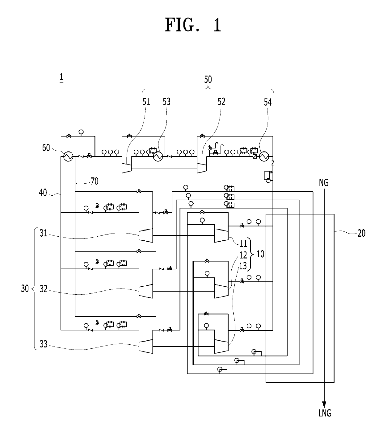
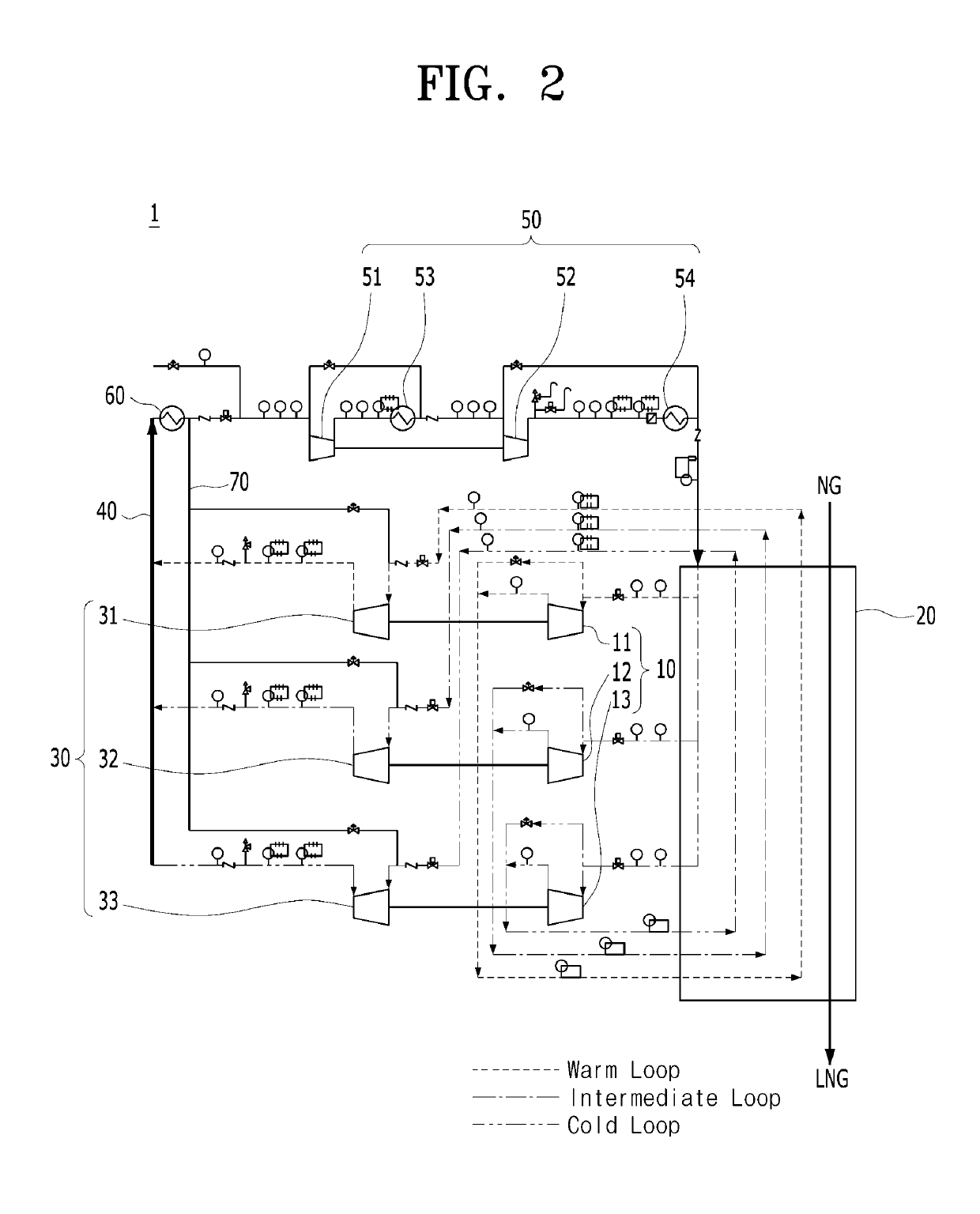
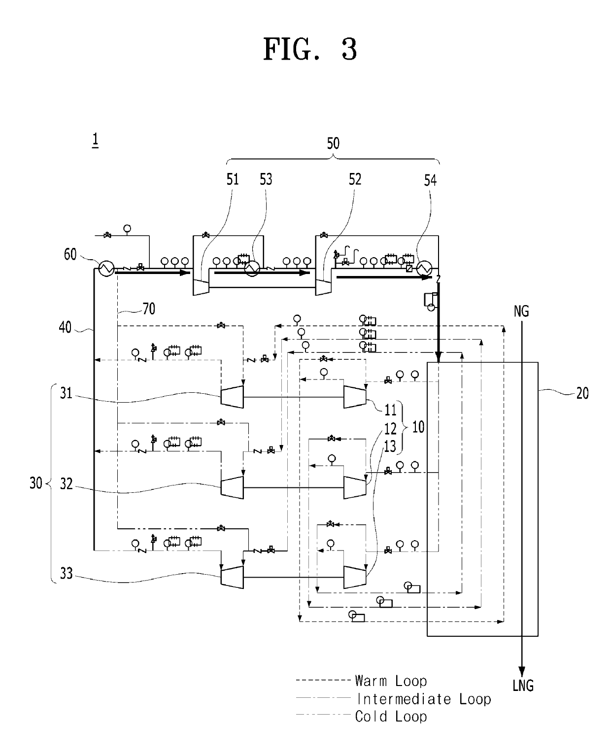
[0017]Hereinafter, a fluid cooling apparatus according to an embodiment of the present invention will be described in detail with reference to FIG. 1.

[0018]FIG. 1 is a schematic conceptual view of a fluid cooling apparatus according to an embodiment of the present invention.

[0019]A fluid cooling apparatus 1 according to an embodiment of the present inv...


PUM


Abstract

A fluid cooling apparatus capable of improving liquefaction efficiency of a fluid by appropriately cooling the fluid in various temperature ranges through a simple process. The fluid cooling apparatus includes an expansion unit including a plurality of expanders, which receive refrigerants through a plurality of paths to expand the refrigerants and discharge the expanded refrigerants having different temperatures, a heat exchanger receiving the refrigerants having different temperatures from the expansion unit to cool the fluid in multistages, a precompression unit including a plurality of precompressors, which receive the refrigerants passing through the heat exchanger to compress the refrigerants and discharge the compressed refrigerants at the same pressure, a mixing tube configured to mix the refrigerants discharged from the precompression unit to supply the mixed refrigerant, and a main compression unit connected to the mixing tube to compress the mixed refrigerant and supply the compressed refrigerant to the expansion unit.

Description

TECHNICAL FIELD[0001]The present invention disclosed herein relates to a fluid cooling apparatus, and more particularly, to a fluid cooling apparatus that is capable of improving liquefaction efficiency of a gas with low energy by appropriately cooling the gas in various temperature ranges through a simple process.BACKGROUND ART[0002]An aqueous mixture extracted from an oil well is separated into water, hydrocarbon-based liquid, and gaseous components in a separator. The gas components separated in the separator forms a natural gas (NG) from which impurities are removed through a pretreatment process of a liquefaction system. The natural gas is supplied to a natural gas liquefaction system and then becomes a liquefied natural gas after a series of processes. Since the natural gas liquefaction system performs liquefaction of the natural gas at a cryogenic temperature, if the natural gas containing heavy hydrocarbon is introduced into the liquefaction system as it is, the natural gas ...

Claims


Application Information

Patent Timeline
IPC IPC(8): F25B9/06F25J1/00F25J1/02F25B31/00F25B41/00
CPCF25B9/06F25J1/0022F25J1/005F25J1/0072F25J1/0204F25J1/0288F25J1/0294F25J1/0298F25B31/008F25B41/003F25J2270/16F25J1/0212F25B1/10F25B2400/075F25B11/02F25B2400/14F25B31/00F25J1/008F25B41/00F25B3/00
Inventor LEE, DONGHUNKIM, MUNGYUMIN, JOONHOPARK, HYUNKILEE, CHIHUN
Owner SAMSUNG HEAVY IND CO LTD
Learn More