Pyroelectric sensor with an electromagnetic shielding including a composite material

Active Publication Date: 2019-06-27
COMMISSARIAT A LENERGIE ATOMIQUE ET AUX ENERGIES ALTERNATIVES
View PDF1 Cites 0 Cited by
  • Summary
  • Abstract
  • Description
  • Claims
  • Application Information

AI Technical Summary

Benefits of technology

The patent describes a technology that uses nanowires and nanotubes to transfer heat quickly in electronic devices. These nanowires and nanotubes have a lengthened structure that allows for limited heat transfer between pixels in a matrix, even if they are only slightly inclined. This results in better heat transfer in the device's shielding layer and reduces heat transfer to other areas. Overall, this technology improves heat transfer and protects the device's pixels from excessive heat.

Problems solved by technology

After several seconds, the temperature of the finger and the temperature of the contact surface are homogenised, and it is no longer possible to obtain a satisfactory contrast.
However, if this stage is constituted of a layer of a material having a too high thermal conductivity, there is a risk that heat propagates laterally in the electromagnetic shielding stage, from one pixel to the other of the sensor.
Conversely, if this stage is constituted of a layer of a material having a too low thermal conductivity, exchanges of heat through this stage are slowed down, also slowing down the reading of the pixels of the sensor.
This slower reading may pose difficulties, in particular for sensors of large dimensions.

Method used


Image

  • Pyroelectric sensor with an electromagnetic shielding including a composite material
  • Pyroelectric sensor with an electromagnetic shielding including a composite material
  • Pyroelectric sensor with an electromagnetic shielding including a composite material

Examples


first embodiment

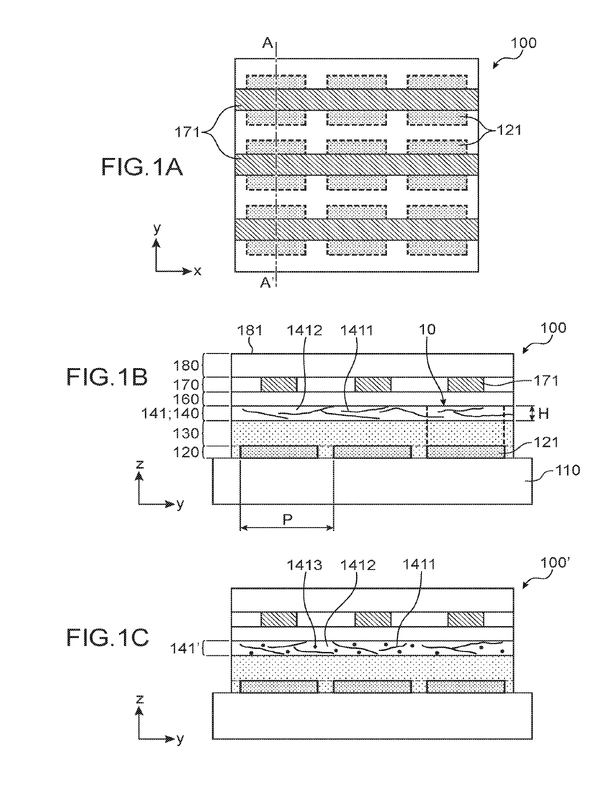
[0049]FIGS. 1A and 1B schematically illustrate a heat pattern sensor according to the invention;

[0050]FIG. 1C illustrates an alternative of the embodiment of FIGS. 1A and 1B;

second embodiment

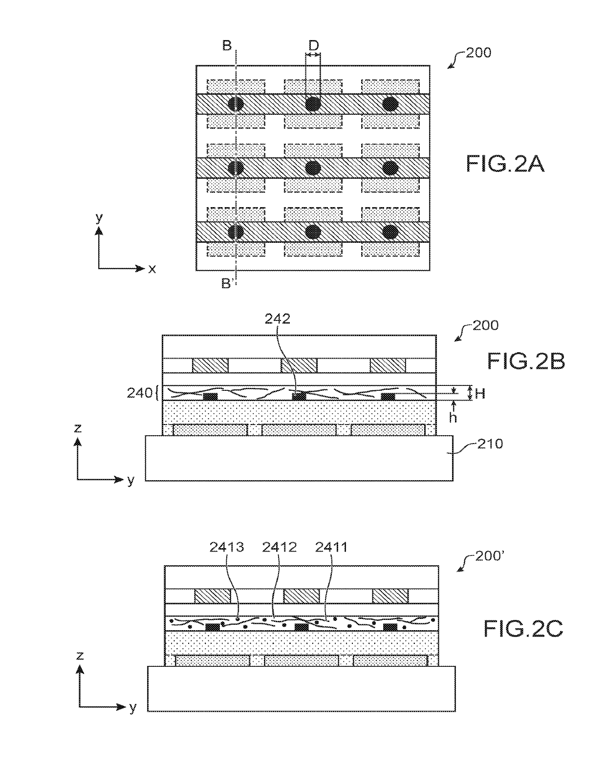
[0051]FIGS. 2A and 2B schematically illustrate a heat pattern sensor according to the invention;

[0052]FIG. 2C illustrates an alternative of the embodiment of FIGS. 2A and 2B;

third embodiment

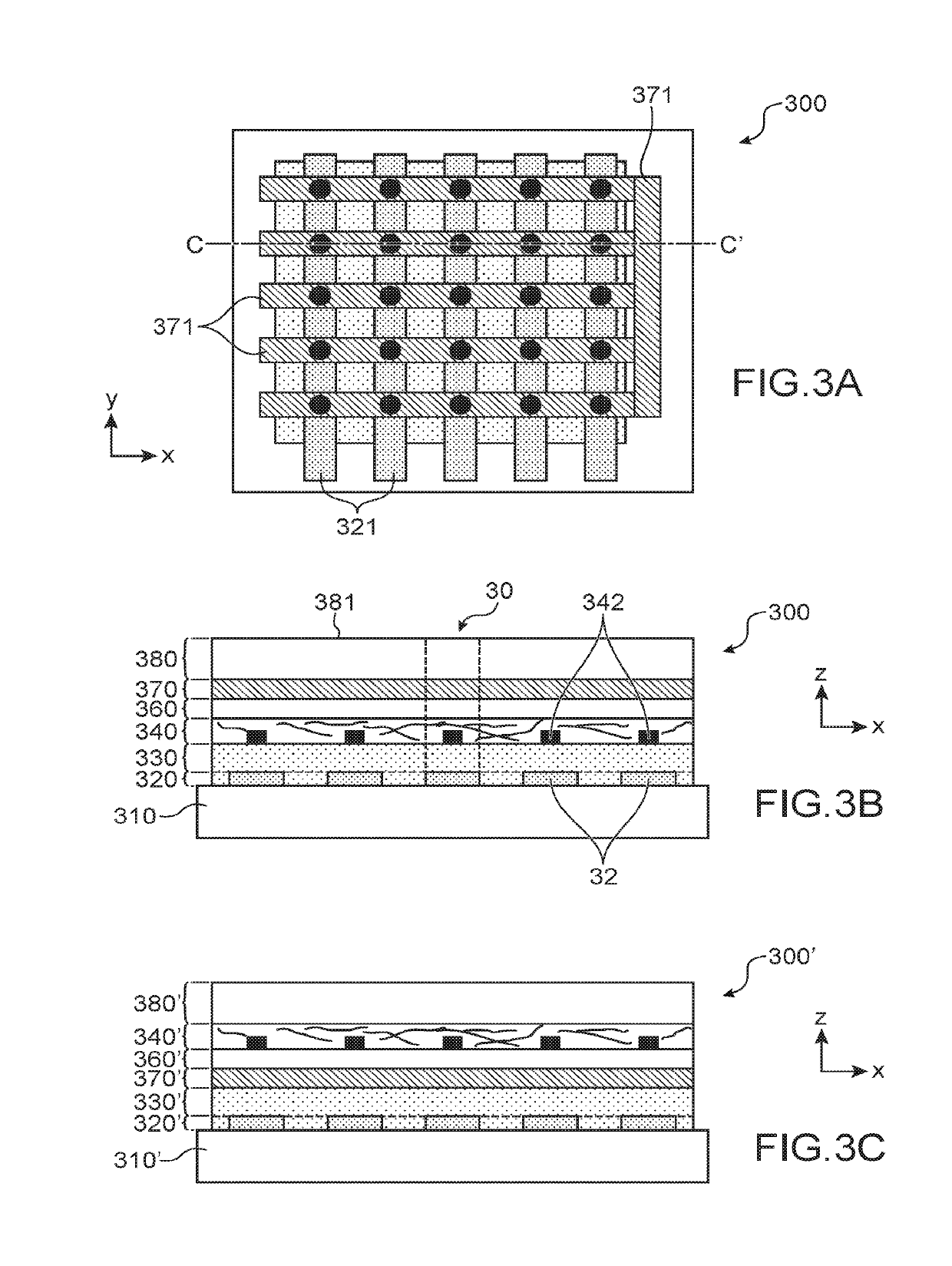
[0053]FIGS. 3A and 3B schematically illustrate a heat pattern sensor according to the invention; and

[0054]FIG. 3C illustrates an alternative of the embodiment of FIGS. 3A and 3B.


PUM


Abstract

The invention relates to a heat pattern sensor including a matrix of pyroelectric capacitances. The sensor further includes an electromagnetic shielding stage, electrically conducting, situated between a stage including a pyroelectric material and a contact surface of the sensor. The electromagnetic shielding stage includes a shielding layer which comprises nanowires and / or nanotubes lying in a surrounding medium. The nanowires and / or nanotubes have a thermal conductivity greater than that of the surrounding medium. A ratio between a distribution pitch of the pixels of the matrix of pixels and a thickness of the shielding layer is greater than or equal to 20. The invention makes it possible to obtain at the same time rapid heat transfers through the electromagnetic shielding stage and low lateral heat transfers, from one pixel to the other of the sensor.

Description

TECHNICAL FIELD[0001]The invention relates to a heat pattern sensor of pyroelectric sensor type. Such a sensor forms for example a papillary print sensor, notably a finger print sensor.PRIOR ART[0002]A pyroelectric sensor exploits the pyroelectric properties of a material, that is to say its capacity to generate electrical charges in response to a variation in temperature.[0003]Such a sensor comprises a matrix of pyroelectric capacitances, each forming a transducer to translate a temporal variation in temperature into an electrical signal.[0004]Each pyroelectric capacitance comprises a pyroelectric material portion, arranged between a lower electrode and an upper electrode. One of the electrodes is placed at a constant potential, and forms a reference electrode. The other electrode, designated charge collection electrode, collects the pyroelectric charges generated by the pyroelectric material in response to a variation in temperature. The charge collection electrode is connected to...

Claims


Application Information

Patent Timeline
IPC IPC(8): G01J5/06G01J5/34
CPCG01J5/06G01J5/34G01J2005/345G01J2005/065G06V40/1329G06V40/1306
Inventor BENWADIH, MOHAMMED
Owner COMMISSARIAT A LENERGIE ATOMIQUE ET AUX ENERGIES ALTERNATIVES
Why Eureka
Try Eureka