Magnetic sensor

a technology of magnetic sensors and sensors, applied in the field of magnetic sensors, can solve the problems of increasing output noise in the long axis direction of giant magnetoresistive thin films, and achieve the effect of enhancing the sensitivity of a magnetic sensor

Active Publication Date: 2019-06-27
TDK CORPARATION
View PDF3 Cites 3 Cited by
  • Summary
  • Abstract
  • Description
  • Claims
  • Application Information

AI Technical Summary

Benefits of technology

[0005]As disclosed in JPH11-87804, the sensitivity of a magnetic sensor is enhanced by providing soft magnetic thin films on both sides of the giant magnetoresistive thin film. In this arrangement, the sensitivity of a magnetic sensor is further enhanced as the soft magnetic thin films (soft magnetic bodies) become wider.

Problems solved by technology

However, output noise in the long axis direction of the giant magnetoresistive thin film, which is perpendicular to the direction of a magnetically sensitive axis in a magnetic field (in this case, the direction of a short axis of the giant magnetoresistive thin film), increases as the soft magnetic thin films (soft magnetic bodies) become wider.

Method used


Image

  • Magnetic sensor
  • Magnetic sensor
  • Magnetic sensor

Examples


Embodiment Construction

[0020]Explanation will be given about an embodiment, as well as modifications of the embodiment.

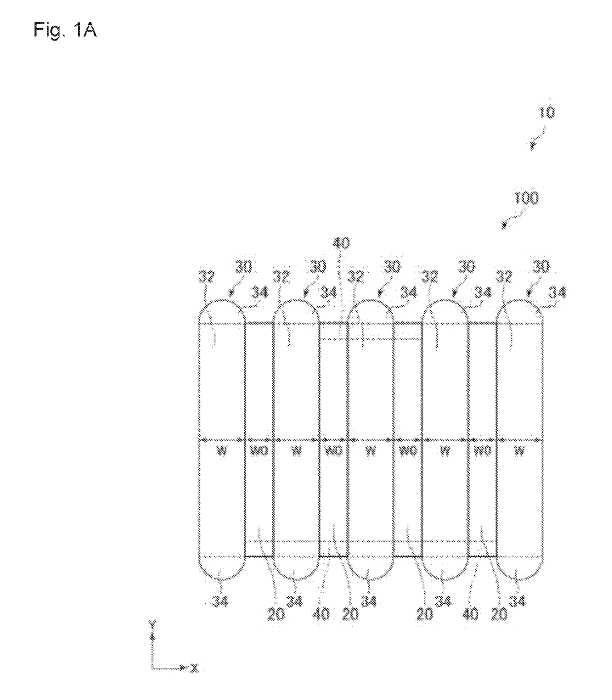
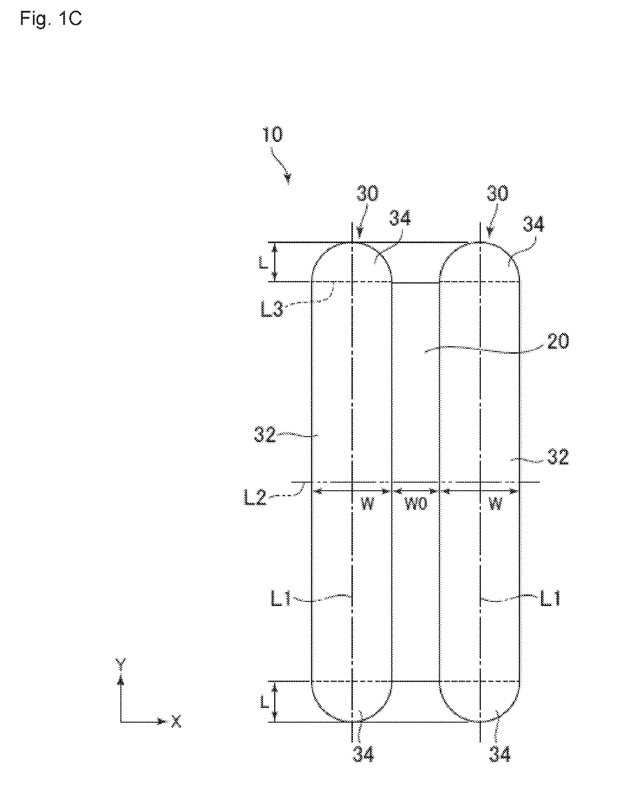
[0021]Magnetic sensor 10 of the embodiment is, for example, a sensor for detecting the position of a moving object (not shown) having a magnet, that is, a position sensor. Magnetic sensor 10 of the embodiment is configured to move relative to the above-mentioned magnet and thereby to detect a change in an external magnetic field that is generated by the magnet, and to calculate the moving distance of the moving object based on the change that is detected. Magnetic sensor 10 of the embodiment has a magnetically sensitive axis, which is the X axis in FIGS. 1A and 10, and detects a change in a magnetic field in the X axis direction that is generated by the moving object. In the following descriptions, the X axis in FIGS. 1A and 10, i.e., the axis parallel to the short axes of element portion 20 and soft magnetic body 30, is referred to as a first axis, and the Y axis in FIGS. 1A and 10, i.e....


PUM

PropertyMeasurementUnit
strain angleaaaaaaaaaa
magnetoresistive effectaaaaaaaaaa

Abstract

A magnetic sensor of the present invention has an elongate element portion having a magnetoresistive effect and a pair of elongate soft magnetic bodies that are arranged along the element portion on both sides of the element portion with regard to a short axis thereof. Each soft magnetic body includes a central portion that is adjacent to the element portion from one end to another end of the element portion with regard to a long axis direction thereof and a pair of end portions that protrude from the central portion in the long axis direction. A width of at least one of the end portions gradually decreases in a direction away from the central portion in at least a part of the end portions in the long axis direction thereof.

Description

BACKGROUND OF THE INVENTIONField of the Invention[0001]The present application is based on, and claims priority from, JP Application No. 2017-250477, filed on Dec. 27, 2017, the disclosure of which is hereby incorporated by reference herein in its entirety.[0002]The present invention relates to a magnetic sensor.Description of the Related Art[0003]As a sensor for detecting the position of a moving object, a magnetic sensor that has an element having a magnetoresistive effect is known (see JPH11-87804). A magnetic sensor moves relative to a magnet and thereby detects a change in an external magnetic field that is generated by the magnet, and calculates the moving distance of the moving object based on the change in the external magnetic field that is detected.[0004]The magnetic sensor that is disclosed in JPH11-87804 has a giant magnetoresistive thin film that exhibits a magnetoresistive effect and soft magnetic thin films, as shown in FIG. 1 thereof. In the magnetic sensor, the gian...

Claims


Application Information

Patent Timeline
Patent Type & Authority Applications(United States)
IPC IPC(8): G01R33/09G11B5/39
CPCG01R33/091G01R33/093G11B5/3906G01R33/098G01B7/02G01B7/00H10N50/10G11B5/398G01R33/0017
Inventor WATANABE, KAZUYA
Owner TDK CORPARATION
Why Eureka
Try Eureka