Composing Microservices through Workflows for Applications in Engineering Design and Manufacturing

Inactive Publication Date: 2019-06-27
PALO ALTO RES CENT INC
View PDF7 Cites 12 Cited by
  • Summary
  • Abstract
  • Description
  • Claims
  • Application Information

AI Technical Summary

Benefits of technology

[0008]Multiple software architectures based on different workflows can be generated from the same collection of microservice com

Problems solved by technology

This means changing or adding new functionality becomes an intricate task which may involve a substantial rewrite of the existing codebase.
Monolithic systems can also require specialized hardware which may be used by a small subset of functional units, resulting in l

Method used


Image

  • Composing Microservices through Workflows for Applications in Engineering Design and Manufacturing
  • Composing Microservices through Workflows for Applications in Engineering Design and Manufacturing
  • Composing Microservices through Workflows for Applications in Engineering Design and Manufacturing

Examples


Embodiment Construction

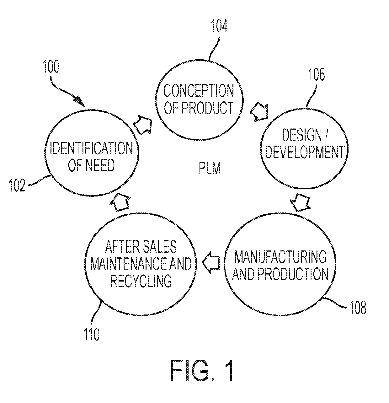
[0021]Presently it is common to have product lifecycle management (PLM) systems for use in one or more of the various areas of PLM (e.g., see FIG. 1) built in a monolithic fashion (i.e. where several software libraries solving distinct applications such as CAD or CAM are bundled into a single package) yielding a single large monolithic executable program that performs numerous distinct design-related tasks spanning from, but not limited to, shape and material synthesis, physical simulation, and manufacturing planning, to detailed optimization, tool-path generation, geometric dimensioning and tolerancing, and machine control for product manufacture. While these monolithic systems are comprised of several functional units, these units are tightly coupled, providing the advantages of an integrated software environment for lifecycle management where relationships between functional units are usually optimized for in-memory performance. However, changing or adding new functionality becom...


PUM


Abstract

An approach to architecting engineering design and digital manufacturing software systems by orchestrating several independently deployable, limited in scope, small software components (i.e., microservices). Interactions between these components are composed via first-order descriptions of workflows, allowing the construction of flexible, scalable, resilient systems.

Description

BACKGROUND[0001]The present disclosure is directed to the development of hardware and software services for use in connection with product lifecycle management (PLM), where today such services are commonly designed and implemented as monolithic systems. PLM systems are, as exemplary shown in FIG. 1, intended to systematically improve and integrate various phases of a product's lifecycle 100, including identification of need 102, conception of the product 104, design / development (including conceptual, preliminary, and detailed design, simulation / analysis, optimization / synthesis) 106, manufacturing / production (including process planning and execution, quality control inspection) 108, and other actions after its sale such as maintenance and recycling 110 (it is understood that FIG. 1 is simply one example of a representation of a PLM environment).[0002]There are various shortcomings in the existing monolithic designs, including but not limited to a tight coupling of the various functio...

Claims


Application Information

Patent Timeline
IPC IPC(8): G06Q10/06G06F17/50
CPCG06Q10/06315G06F17/5009G06Q10/067G06F30/20
Inventor NELATURI, SAIGOPALPEREZ, ALEXANDREBEHANDISH, MORAD
Owner PALO ALTO RES CENT INC
Why Eureka
Try Eureka