Circuit board, connector assembly and cable harness

Active Publication Date: 2019-06-27
JAPAN AVIATION ELECTRONICS IND LTD
View PDF0 Cites 2 Cited by
  • Summary
  • Abstract
  • Description
  • Claims
  • Application Information

AI Technical Summary

Benefits of technology

[0014]The circuit board of the present invention is configured as follows; the first trace portions have the lengths equal to each other, the inner trace portion has the length equal to the length of the outer trace portion, and the second trace portions have the lengths equal to each other. Since this configuration provides that differential traces of a pair of the present invention have lengths equal to each other, occurrence of skew is reduced between the differential traces. In addition, the ground conductor portion, which is connected through the via (via hole) with the ground pattern formed on the second wiring laye

Problems solved by technology

Accordingly, the cable harness having this structure is unfavorable.
Accordingly, skew occurs between a differential signal pair which passes through the modified differential traces, and thereby a transmission error occurs.
However, the remodeled shape of the inne

Method used


Image

  • Circuit board, connector assembly and cable harness
  • Circuit board, connector assembly and cable harness
  • Circuit board, connector assembly and cable harness

Examples


Example

[0023]While the invention is susceptible to various modifications and alternative forms, specific embodiments thereof are shown by way of example in the drawings and will herein be described in detail. It should be understood, however, that the drawings and detailed description thereto are not intended to limit the invention to the particular form disclosed, but on the contrary, the intention is to cover all modifications, equivalents and alternatives falling within the spirit and scope of the present invention as defined by the appended claims.

DESCRIPTION OF PREFERRED EMBODIMENTS

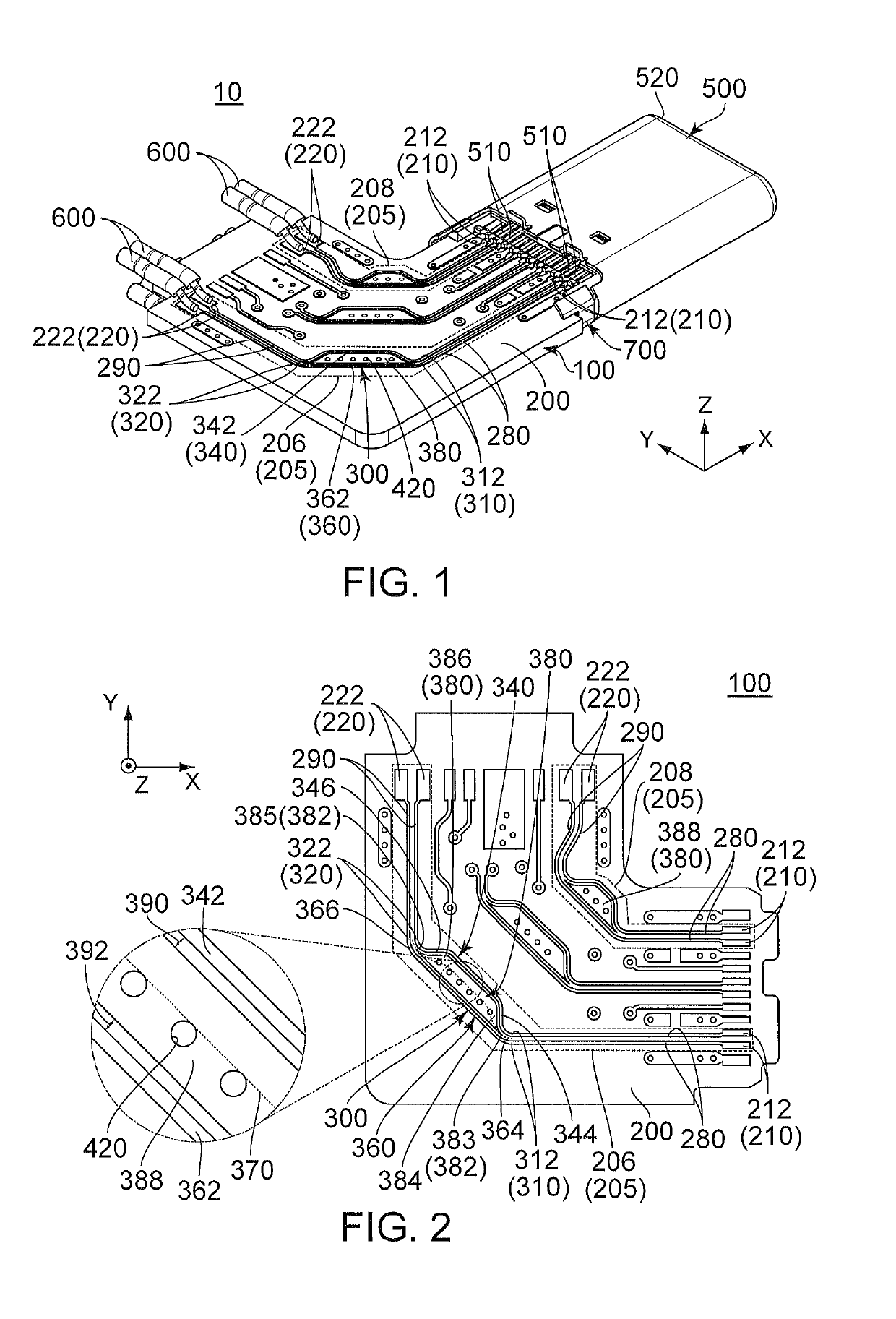
[0024]As shown in FIG. 1, a cable harness 10 according to an embodiment of the present invention comprises a connector assembly 700 and a cable 600. The cable 600 functions as a second connecting object 600. Although the cable 600 shown in FIG. 1 is simply illustrated as a plurality of insulated single wires, an actual cable 600 is a multi-conductor cable. Specifically, the actual cable 600 comprises a plur...


PUM


Abstract

A circuit board comprises at least a first wiring layer, a second wiring layer and a via. The first wiring layer is formed with a pair of first ends, a pair of second ends, a coupling portion, a pair of first trace portions and a pair of second trace portions. The coupling portion has a pair of first coupling points, a pair of second coupling points, an inner trace portion, an outer trace portion and a ground conductor portion. The inner trace portion has a length equal to a length of the outer trace portion. The ground conductor portion is arranged between the inner trace portion and the outer trace portion. The second wiring layer is formed with a ground pattern. The ground conductor portion is connected with the ground pattern through the via.

Description

CROSS REFERENCE TO RELATED APPLICATIONS[0001]This application is based on and claims priority under 35 U.S.C. § 119 to Japanese Patent Application No. JP2017-247425 filed Dec. 25, 2017, the contents of which are incorporated herein in their entireties by reference.BACKGROUND OF THE INVENTION[0002]This invention relates to a circuit board, a connector assembly and a cable harness.[0003]Referring to FIG. 7, JP-A 2004-14800 (Patent Document 1) discloses a circuit board 900 on which a pair of differential traces 920 is formed. The differential traces 920 have a pair of first trace portions 921, a pair of second trace portions 928 and a coupling portion 930. The first trace portions 921, the coupling portion 930 and the second trace portions 928 are coupled in this order. The coupling portion 930 has a pair of first coupling portions 932, a pair of third trace portions 933, a pair of through holes 934, a pair of fourth trace portions 936 and a pair of second coupling portions 937. The co...

Claims


Application Information

Patent Timeline
IPC IPC(8): H05K1/02
CPCH05K1/0222H05K1/0228H01R12/53H01R12/722H05K2201/09027H05K2201/09227H05K2201/09236H05K2201/09272H05K2201/09618H05K1/0245H05K1/0218H01R13/6471H01R24/60H05K1/0248H05K1/117H05K2201/10356H05K2201/09672
Inventor TODA, KENTARO
Owner JAPAN AVIATION ELECTRONICS IND LTD
Why Eureka
Try Eureka