Lighting circuit

Active Publication Date: 2019-07-04
KOITO MFG CO LTD
View PDF0 Cites 2 Cited by
  • Summary
  • Abstract
  • Description
  • Claims
  • Application Information

AI Technical Summary

Benefits of technology

The present invention provides a lighting circuit with low costs. By not turning on multiple light-emitting elements simultaneously, the voltage drops across all elements are reduced, which allows the required breakdown voltage to be lower and the output voltage range of the constant current driving circuit to be reduced. This arrangement reduces the costs of the lighting circuit.

Problems solved by technology

However, the high-beam mode has a problem of imparting glare to a pedestrian or otherwise a driver of a vehicle ahead of the vehicle.
However, such a high-breakdown-voltage IC that supports a high breakdown voltage of 100 V or more leads to a problem of high costs.
Furthermore, the constant current converter 22 is required to be designed to support a high breakdown voltage of VOUT(MAX)=96 V, leading to a problem of high costs.
However, the lighting circuit 20S shown in FIG. 2 requires two constant current converters 22, leading to a problem of high costs.

Method used


Image

  • Lighting circuit
  • Lighting circuit
  • Lighting circuit

Examples


first modification

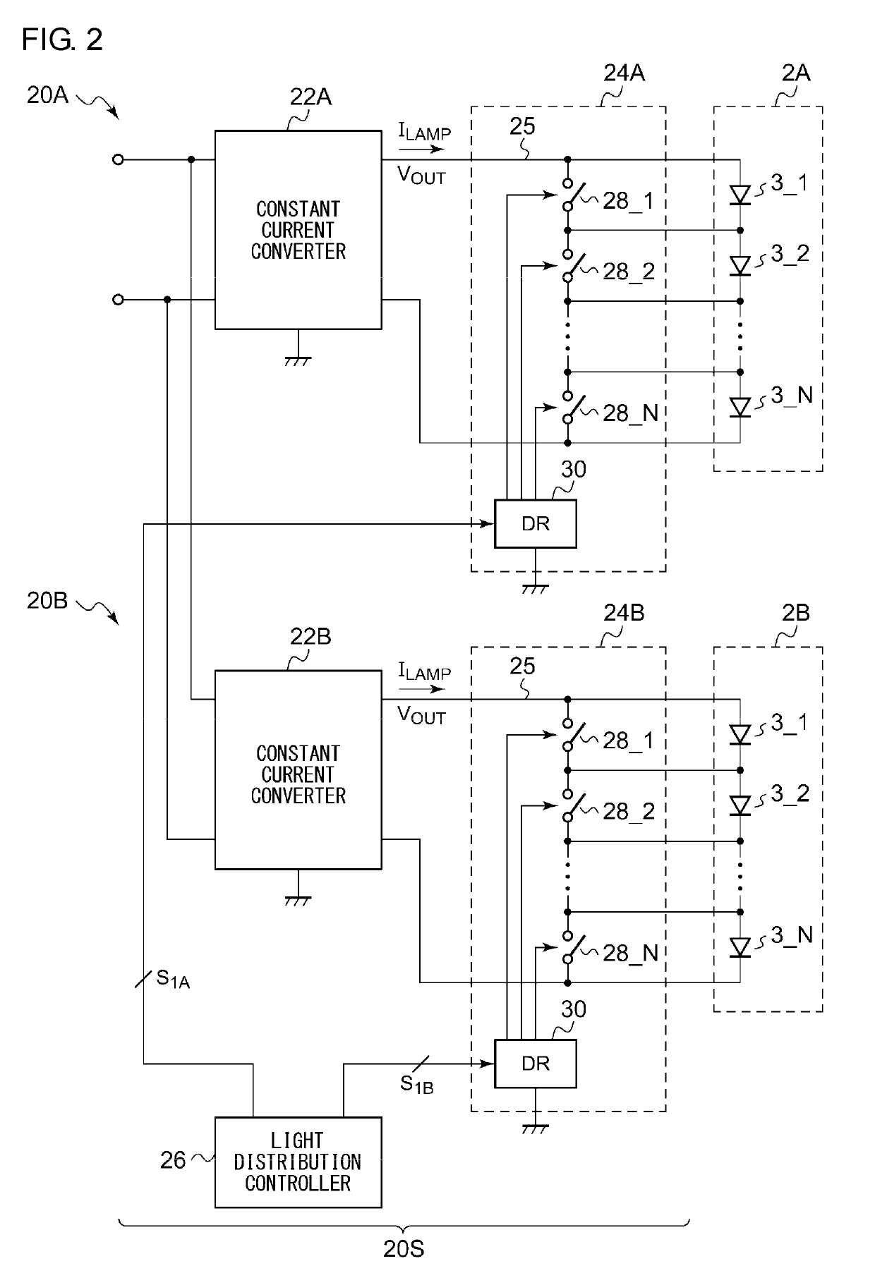
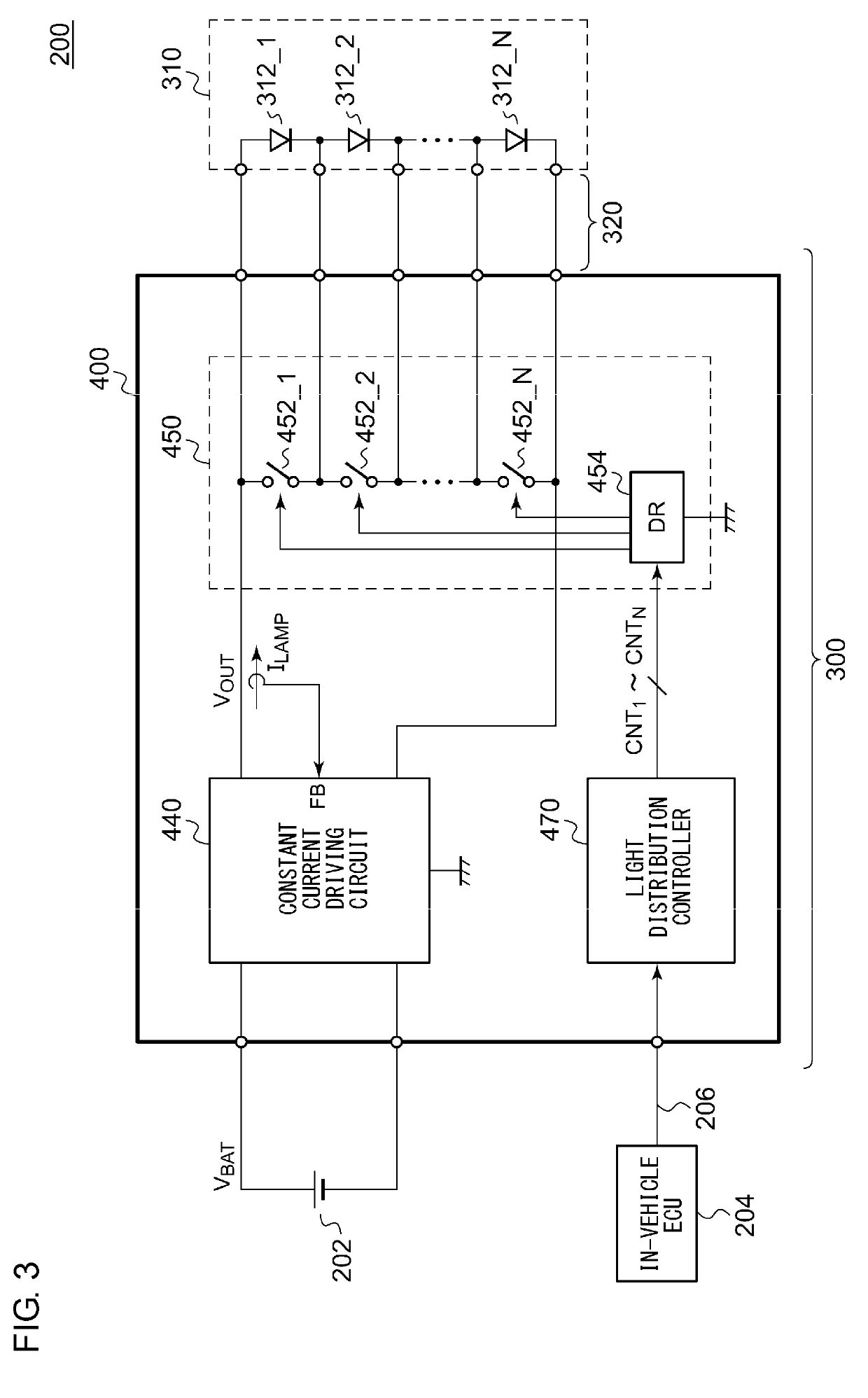
[0087]FIG. 10 is a block diagram showing a lighting circuit 400a according to a first modification. In this modification, the bypass switch circuit 450 is configured as multiple (two) separate ICs. For example, in a case in which N=24 channels, the lighting circuit 400a is provided with two light sources 310 each including twelve light-emitting elements 312. The bypass switch circuit 450 is provided for each of the light sources 310. The light distribution controller 470 supplies a control signal CNT for each of the bypass switch circuits 450A and 450B. With this arrangement, each bypass switch circuit 450 may be configured as a low-breakdown-voltage IC that supports a breakdown voltage that is lower than (N×VF). Furthermore, this arrangement allows the range of variation of the output voltage VOUT of the constant current driving circuit 440 to be reduced. This arrangement allows constraints on the circuit design to be relaxed.

second modification

[0088]In a case in which the light distribution pattern can be switched and selected from among multiple light distribution patterns, each pair of two bypass switches may be recombined for each light distribution pattern.

third modification

[0089]The constant current driving circuit 440 may be configured as a constant-current-control step-up / step-down converter. Also, the constant current driving circuit 440 may be configured as a combination of a step-up, step-down, or otherwise step-up / step-down switching converter and a constant current circuit.


PUM


Abstract

A lighting circuit drives a light source including N (N represents an integer of 2 or more) multiple light-emitting elements coupled in series. A bypass switch circuit includes N multiple bypass switches, each coupled in parallel to a corresponding light-emitting element. A constant current driving circuit supplies a driving current stabilized to a target current to the light source. A light distribution controller controls the bypass switch circuit. For a given light distribution pattern, the duty ratio Di(%) is determined for each of the N multiple light-emitting elements. Multiple light-emitting elements are formed as control units having a sum total of duty ratios that is less than 100%. The light distribution controller controls the multiple bypass switches such that the multiple light-emitting elements included in the same control unit are not turned on at the same time.

Description

BACKGROUND OF THE INVENTION1. Field of the Invention[0001]The present invention relates to a lighting device to be used in a vehicle or the like.2. Description of the Related Art[0002]Typical automotive lamps are capable of switching between a low-beam mode and a high-beam mode. The low-beam mode is used to illuminate a close range with a predetermined light intensity. In the low-beam mode, light distribution is determined so as to prevent glare being imparted to an oncoming vehicle or a leading vehicle. The low-beam mode is mainly used when the vehicle is traveling in an urban area. In contrast, the high-beam mode is used to illuminate a distant range over a wide area ahead of the vehicle with a relatively high light intensity. The high-beam mode is mainly used when the vehicle is traveling at high speed along a road where there are a small number of oncoming vehicles and leading vehicles. Accordingly, the high-beam mode provides the driver with high visibility, which is an advanta...

Claims


Application Information

Patent Timeline
IPC IPC(8): B60Q1/14
CPCB60Q1/1423H05B45/48F21S41/151F21S41/663B60Q1/1415H05B47/17B60Q1/04H05B47/10Y02B20/40
Inventor MARUYAMA, YUTAMURAKAMI, KENTAROUMURAMATSU, TAKAO
Owner KOITO MFG CO LTD
Why Eureka
Try Eureka