
Heat exchange-type ventilation device

a ventilation device and heat exchange technology, applied in ventilation systems, heating types, lighting and heating apparatus, etc., can solve problems such as complex installation on site, and achieve the effects of simplifying installation, enhancing temperature adjustment efficiency of unitary air conditioning, and simplifying on-site installation

Inactive Publication Date: 2019-07-04
PANASONIC INTELLECTUAL PROPERTY MANAGEMENT CO LTD
View PDF0 Cites 7 Cited by
  • Summary
  • Abstract
  • Description
  • Claims
  • Application Information

AI Technical Summary

Benefits of technology

The present patent is about a heat exchange-type ventilation device that can automatically adjust its airflow rate using an airflow rate adjustment damper. This device can simplify on-site installation, which means it can be installed more easily and quickly. However, this feature may not be necessary for all configurations of the device. Overall, the patent provides a solution for improving the installation process of heat exchange-type ventilation devices.

Problems solved by technology

However, this configuration has a problem that it is required to determine the angle (the opening area) of the airflow rate adjustment damper while measuring an airflow rate, and this makes on-site installation complicated.

Method used


Image

  • Heat exchange-type ventilation device
  • Heat exchange-type ventilation device
  • Heat exchange-type ventilation device

Examples


embodiment 1

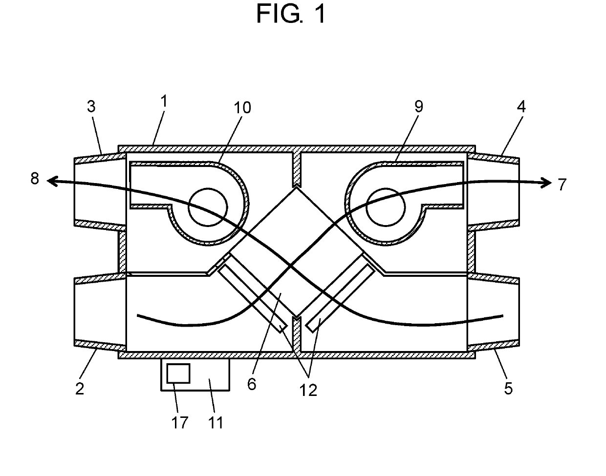
[0029]An interior configuration, an air supply path, and an exhaust path of a heat exchange-type ventilation device of Embodiment 1 will be described using FIG. 1.

[0030]FIG. 1 is a top cross-sectional view of the heat exchange-type ventilation device of Embodiment 1.

[0031]As illustrated in FIG. 1, heat exchange-type ventilation device 1 includes: outside-air inlet port 2 and room-air exhaust port 3 which are provided in one side face of a box-shaped body of heat exchange-type ventilation device 1; and outside-air supply port 4 and room-air inlet port 5 which are provided in another side face opposed to the one side face.

[0032]Heat exchange-type ventilation device 1 further includes air supply path 7 into which fresh outside air (supply air) is drawn from outside-air inlet port 2 provided in the side face of the body and through which the air is supplied to a room from outside-air supply port 4 via heat exchange element 6 provided inside heat exchange-type ventilation device 1.

[0033]...

embodiment 2

[0066]Next, a heat exchange-type ventilation device of Embodiment 2 will be described.

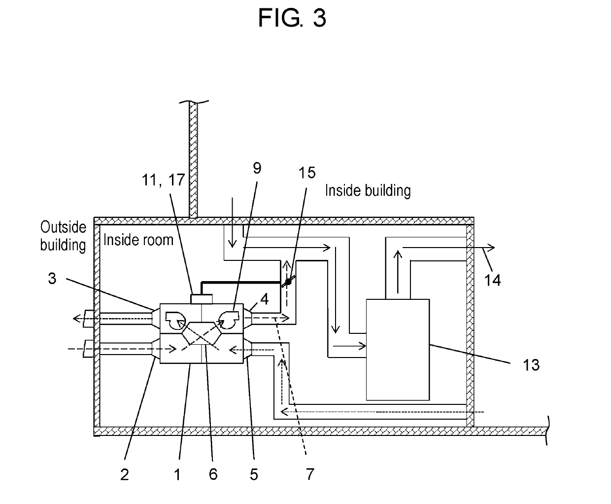
[0067]In the case where an air supply path (or an exhaust path) of a conventional heat exchange-type ventilation device is connected to a circulating air path of unitary air conditioning, the unitary air conditioning communicates with outside air via the heat exchange-type ventilation device, and therefore, when outside air is introduced at the time of operation of unitary air conditioning, the temperature adjustment efficiency of the unitary air conditioning is sometimes lower than that in a case in which indoor circulation is performed without introducing outside air.

[0068]Hence, an object of Embodiment 2 is to achieve a heat exchange-type ventilation device capable of, when a room temperature is not within a predetermined range of a set temperature of unitary air conditioning, enhancing the temperature adjustment efficiency of the unitary air conditioning by preventing outside air from being int...


PUM


Abstract

Provided is a heat exchange-type ventilation device (1) comprising: an air supply blower including an air supply motor; an exhaust blower including an exhaust motor; an air supply path (7) through which air is sent to a room from outside by the air supply blower: an exhaust path through which air is sent from the room to outside by the exhaust blower: a heat exchange element provided at a position at which the air supply path (7) and the exhaust path intersect, the heat exchange element being configured to exchange heat between room air and outside air at the time of ventilation; and a current detector configured to detect a current flowing through the air supply motor. Using a controller (11), the heat exchange-type ventilation device controls the number of revolutions of the air supply motor. The air supply path is connected to a circulating air path (14) of unitary air conditioning (13), and the controller (11) changes the opening area of an airflow rate adjustment damper (15) provided in the air supply path (7) so that a current value of the air supply motor, the current value being detected by the current detector, falls within a predetermined range of a target current value.

Description

TECHNICAL FIELD[0001]The present disclosure relates to a heat exchange-type ventilation device.BACKGROUND ART[0002]As a conventional ventilation device configured to exchange heat between outside air and room air, there is known a heat exchange-type ventilation device that is installed in a building and configured to introduce outside air from an outside-air inlet port and supply the air to a room via a built-in heat exchange element (for example, refer to Patent Literature 1).[0003]Hereinafter, this heat exchange-type ventilation device will be described with reference to FIG. 11.[0004]FIG. 11 is a configuration diagram illustrating a top view of the conventional heat exchange-type ventilation device.[0005]As illustrated in FIG. 11, ventilation device body 201 is installed in an attic space or a ceiling space inside a building.[0006]Fresh outside air is introduced from outside-air inlet port 202, flows through built-in heat exchange element 203, and is supplied to a room via indoor...

Claims


Application Information

Patent Timeline
Patent Type & Authority Applications(United States)
IPC IPC(8): F24F12/00F24F7/08F24F13/10F24F13/30F24F11/00F24F11/77
CPCF24F12/006F24F7/08F24F13/10F24F13/30F24F11/0001F24F11/77F24F2110/10F24F11/74Y02B30/70
Inventor IIO, KOUJIFUNADA, NAOYUKI
Owner PANASONIC INTELLECTUAL PROPERTY MANAGEMENT CO LTD
Learn More