
Centering devices for use with a valve prosthesis delivery system and methods of use thereof

a technology of centering device and valve prosthesis, which is applied in the field of valve prosthesis, can solve the problems of valve not opening properly, insufficiency or regurgitation, stenosis and insufficiency,

Active Publication Date: 2019-07-11
MEDTRONIC VASCULAR INC
View PDF0 Cites 0 Cited by
  • Summary
  • Abstract
  • Description
  • Claims
  • Application Information

AI Technical Summary

Benefits of technology

The centering devices enable precise positioning of the valve prosthesis, reducing the risk of dislodgement and leakage, thereby improving the success rate of valve implantation and minimizing physiological consequences for the patient.

Problems solved by technology

Problems that may develop with valves include stenosis in which a valve does not open properly, and / or insufficiency or regurgitation in which a valve does not close properly.
Stenosis and insufficiency may occur concomitantly in the same valve.
The effects of valvular dysfunction vary, with regurgitation or backflow typically having relatively severe physiological consequences to the patient.
Although transcatheter delivery methods have provided safer and less invasive methods for replacing a defective native heart valve, complications may arise including vessel trauma due to percutaneous delivery within highly curved anatomy and / or due to a large delivery profile of the prosthesis, inaccurate placement of the valve prosthesis, conduction disturbances, coronary artery obstruction, and / or undesirable paravalvular leakage and / or regurgitation at the implantation site.
More particularly, for example, if a prosthesis is not longitudinally centered relative to the native annulus, i.e., a prosthesis is positioned too deep or too shallow relative to the native annulus or is placed unevenly within the native annulus in terms of depth, the deployed prosthesis may cause conduction disturbances.
In another example, if a prosthesis is not circumferentially centered relative to the native annulus, the deployed prosthesis may dislodge from the implantation site and / or undesirable paravalvular leakage and / or regurgitation may occur.

Method used


Image

  • Centering devices for use with a valve prosthesis delivery system and methods of use thereof
  • Centering devices for use with a valve prosthesis delivery system and methods of use thereof
  • Centering devices for use with a valve prosthesis delivery system and methods of use thereof

Examples


Embodiment Construction

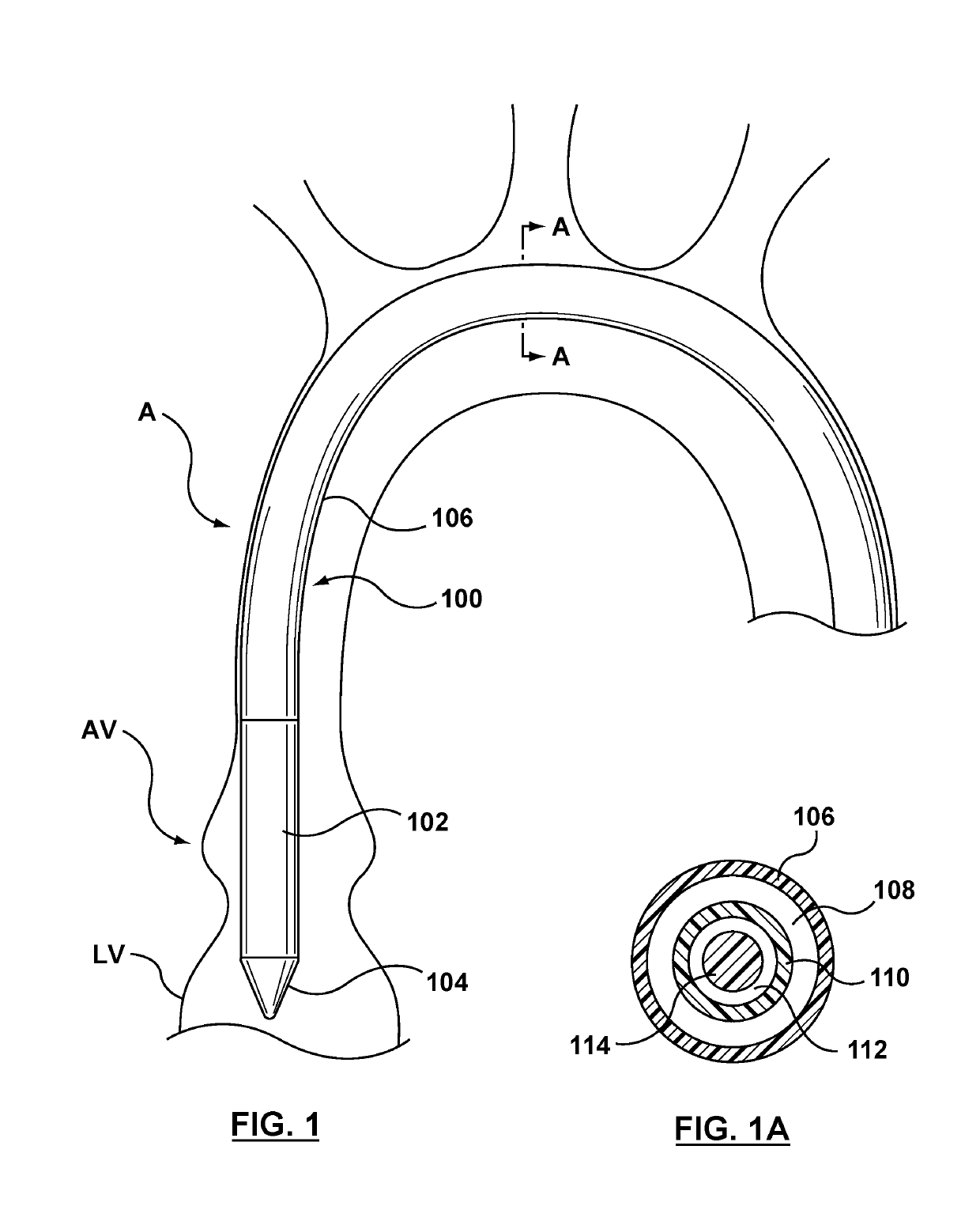
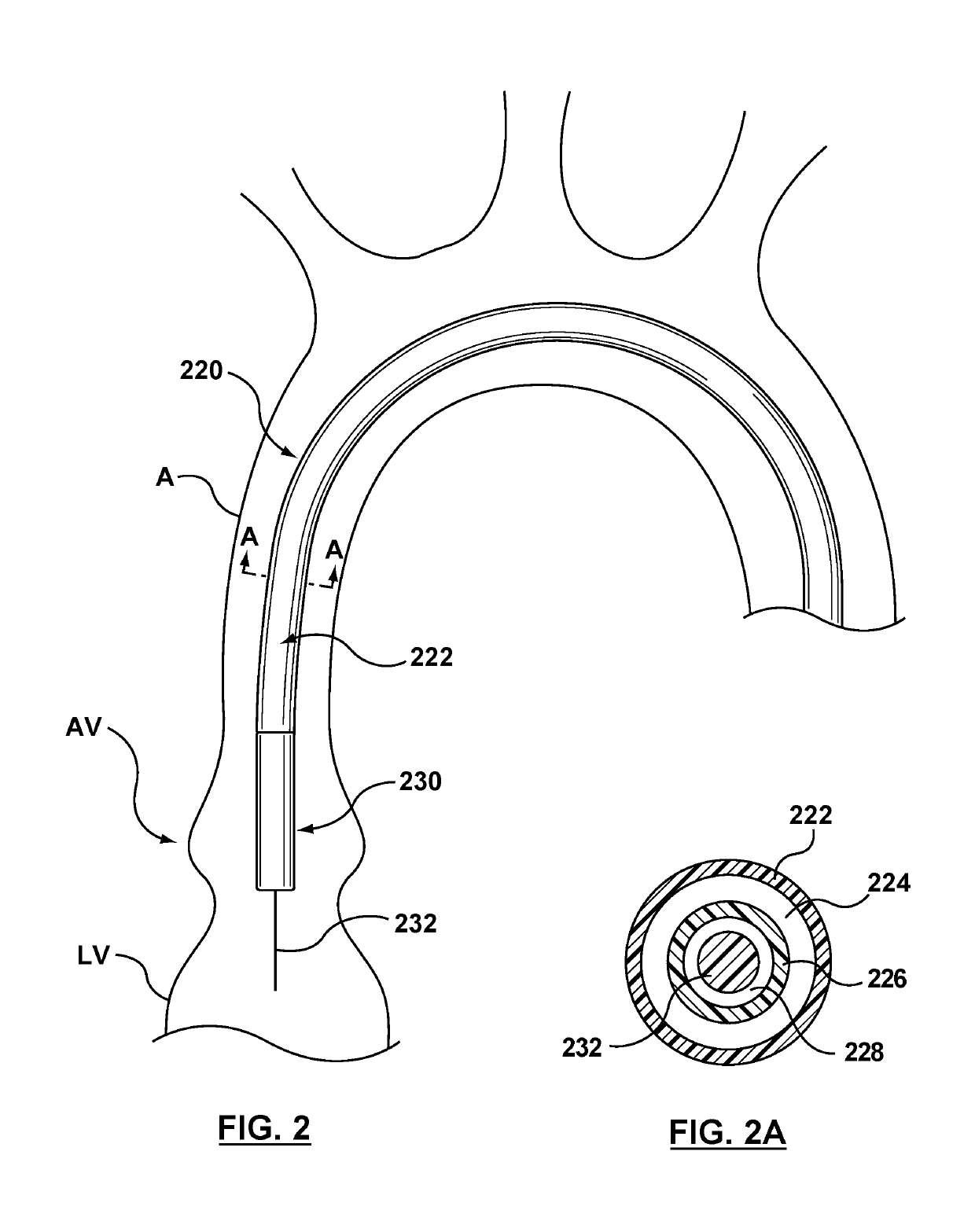
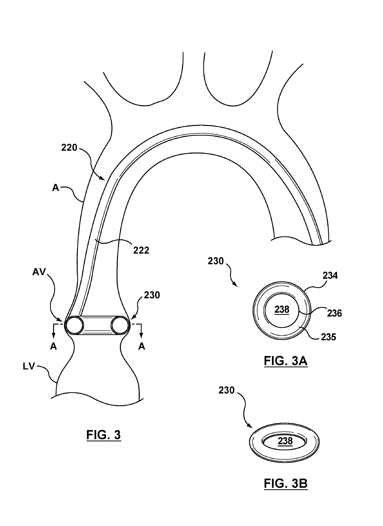
[0040]Specific embodiments of the present invention are now described with reference to the figures, wherein like reference numbers indicate identical or functionally similar elements. Unless otherwise indicated, the terms “distal” and “proximal” are used in the following description with respect to a position or direction relative to the treating clinician. “Distal” and “distally” are positions distant from or in a direction away from the clinician, and “proximal” and “proximally” are positions near or in a direction toward the clinician. In addition, the term “self-expanding” is used in the following description and is intended to convey that the structures are shaped or formed from a material that can be provided with a mechanical memory to return the structure from a compressed or constricted delivery configuration to an expanded deployed configuration. Non-exhaustive exemplary self-expanding materials include stainless steel, a pseudo-elastic metal such as a nickel titanium all...


PUM


Abstract

Embodiments hereof relate to centering devices for use with a valve delivery system and methods of delivering a valve prosthesis within a vasculature. A valve centering catheter is configured for use with a valve delivery system. The valve centering catheter includes a circumferential centering device at a distal portion thereof, and the circumferential centering device defines a central opening there-through when in an expanded configuration. The circumferential centering device is annular or has a C-shaped cross-section. The valve delivery system is tracked through the vasculature until the valve prosthesis is positioned through the central opening of the expanded circumferential centering device. The valve centering catheter may alternatively include a longitudinal centering device which acts as a marker for depth control during delivery of a valve delivery system, which may include an integral circumferential centering device.

Description

CROSS-REFERENCE TO RELATED APPLICATIONS[0001]This application claims the benefit of U.S. Provisional Patent Application Ser. No. 62 / 115,473, filed Feb. 12, 2015, which is hereby incorporated by reference in its entirety for all purposes.FIELD OF THE INVENTION[0002]The invention relates to valve prostheses and more particularly to centering devices configured for use with a valve delivery system for positioning a valve prosthesis in situ.BACKGROUND OF THE INVENTION[0003]A human heart includes four heart valves that determine the pathway of blood flow through the heart: the mitral valve, the tricuspid valve, the aortic valve, and the pulmonary valve. The mitral and tricuspid valves are atrioventricular valves, which are between the atria and the ventricles, while the aortic and pulmonary valves are semilunar valves, which are in the arteries leaving the heart. Ideally, native leaflets of a heart valve move apart from each other when the valve is in an open position, and meet or “coapt...

Claims


Application Information

Patent Timeline
Patent Type & Authority Applications(United States)
IPC IPC(8): A61F2/24
CPCA61F2/2427A61F2/2436
Inventor WHITE, FRANK
Owner MEDTRONIC VASCULAR INC
Features
  • Generate Ideas
  • Intellectual Property
  • Life Sciences
  • Materials
  • Tech Scout
  • Unparalleled Data Quality
  • Higher Quality Content
  • 60% Fewer Hallucinations
Learn More