
Method for monitoring a battery

Inactive Publication Date: 2019-07-11
ROBERT BOSCH GMBH
View PDF0 Cites 17 Cited by
  • Summary
  • Abstract
  • Description
  • Claims
  • Application Information

AI Technical Summary

Benefits of technology

The patent describes a system that uses data from batteries to predict when they'll fail and allow for better planning of battery replacement. This system can also prevent vehicles from driving when their battery is failing, which could cause damage to the vehicle's electrical system. The system calculates reliability indicators and communicates the data to a central unit to improve the predictive model. Overall, the system helps to prolong the life of batteries and prevent damage to vehicles.

Problems solved by technology

Because the steerability of the vehicle is not then incapacitated, but merely becomes stiffer, the failure of the vehicle electrical system is generally accepted in currently produced vehicles.
This has the consequence that up until the termination of the highly automated driving function, the driver's function as a sensory, regulating, mechanical, and energetic fallback level will be limited.
If the supply of energy to the safety-relevant components fails, the vehicle can no longer be controlled by the highly or fully automated function, because all of the functions described above, such as environmental recognition and trajectory planning and implementation, are then no longer available.
From the point of view of product safety, this places very high demands on the vehicle electrical system.
It is to be noted that component failure due to wear is the fundamental cause of a large number of vehicle network states that are safety-relevant in the context of new areas of application.

Method used


Image

  • Method for monitoring a battery
  • Method for monitoring a battery
  • Method for monitoring a battery

Examples


case i

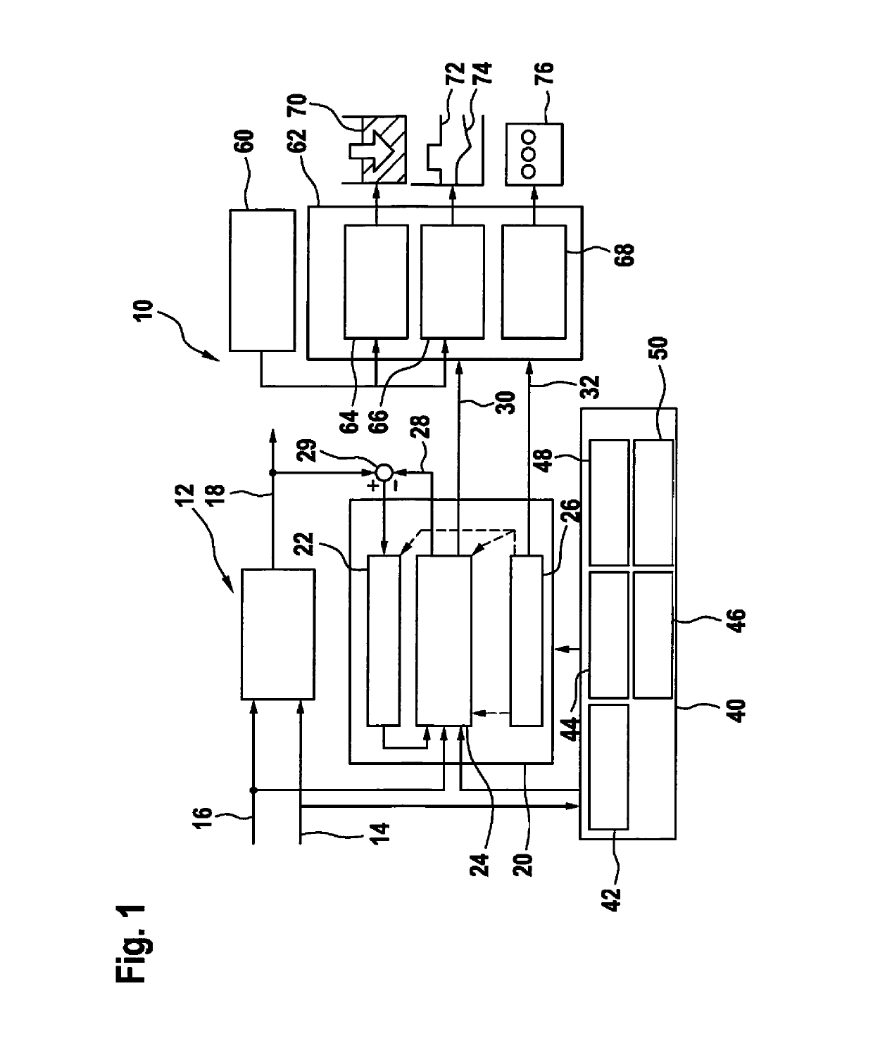
[0098] higher-level control device queries the operating mode and its duration, i.e. the operating strategy is known.

[0099]Example: the driver inputs a destination to the navigation device, and the system control then makes a query concerning the authorization of operating modes and their duration.

[0100]For the queried parameters, namely duration, operating mode, and operating strategy, the “required” reference cycle number is ascertained and is added to the previously seen load at the reference level. It is now checked whether the defined reliability boundary value is maintained. If it is maintained, then the queried case is authorized; otherwise not.

case ii

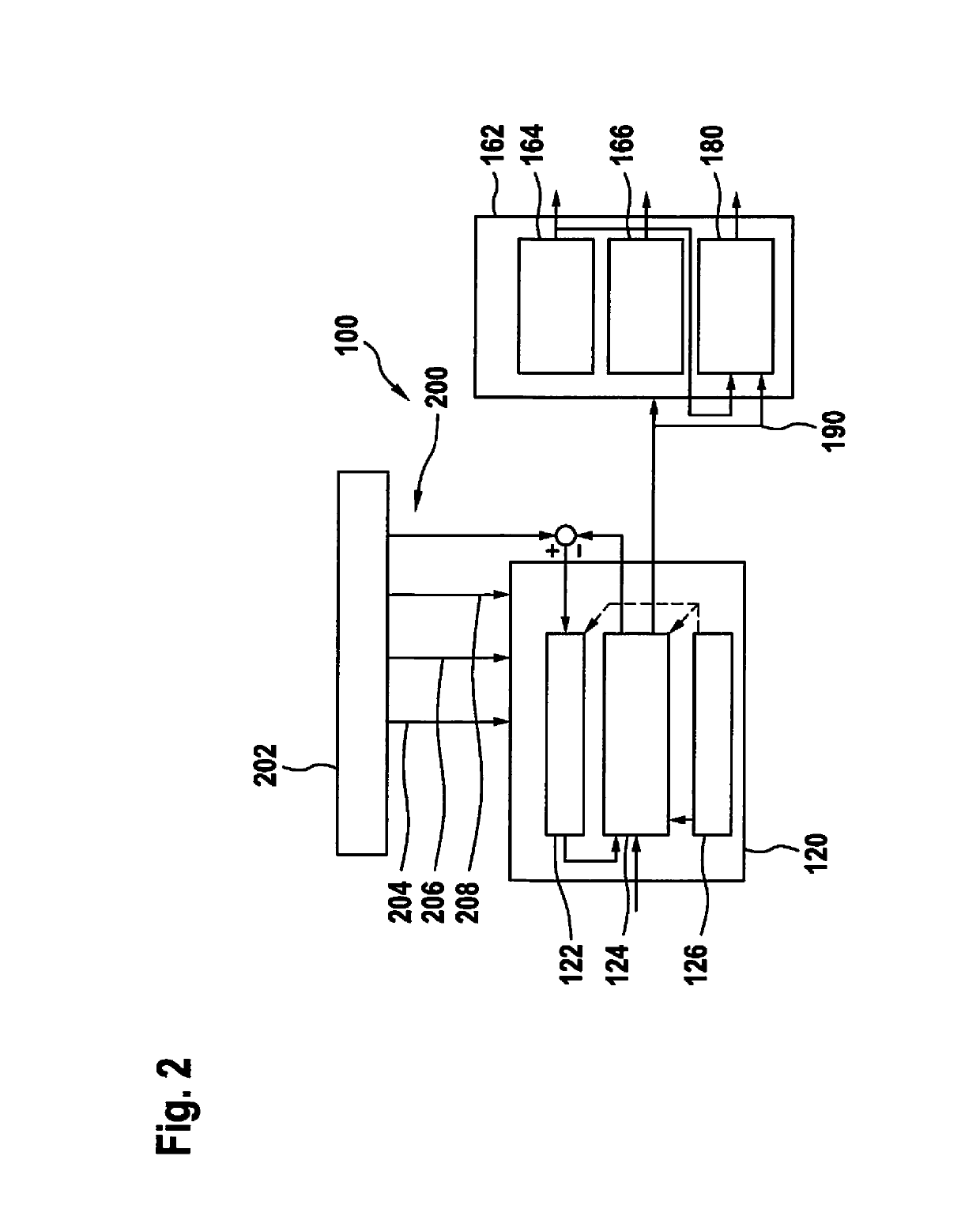
[0101] the higher-level control device generally continuously queries the battery sensor or calculating control device, or the battery sensor or calculating control device continuously reports remaining durations for all the operating modes to the higher-level control device.

[0102]In case II, for all possible combinations of operating modes and operating strategies the duration until the defined reliability boundary value is reached is ascertained and is communicated to the higher-level control device. Thus, the time durations are available specifying in each case how long driving is to be permitted to take place, and there is a time-limited authorization of the functions. If the vehicle is in a combination of operating mode and operating strategy in which battery failure is soon impending, then a change can be made to a combination that better protects the battery, or the transition to the safe state or driver takeover can be introduced.

[0103]Concerning the choice of the safe stop ...


PUM


Abstract

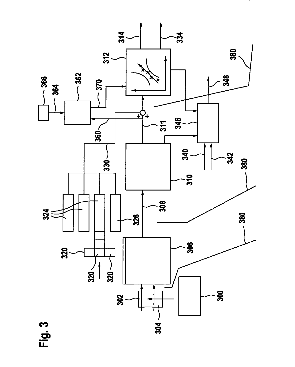
A method and a system are presented for monitoring a battery in a motor vehicle. In the method, a first module ascertains operating quantities of the battery. Variables that represent the operating quantities are compared with a load capacity model in order to ascertain quantities characterizing the reliability of the battery, so that a future behavior of the battery can be predicted.

Description

FIELD OF THE INVENTION[0001]The present invention relates to a method for monitoring a battery, in particular a battery in a motor vehicle, and to a system for carrying out the method.BACKGROUND INFORMATION[0002]A vehicle electrical system is the totality of the electrical components or consumers of a motor vehicle. This network has the task of supplying energy to the electrical consumers. As energy storage devices in vehicle electrical systems, for example batteries are used. In today's vehicles, if the energy supply fails due to a fault in the vehicle electrical system or in a component of the vehicle electrical system, e.g. caused by aging, then important functions, such as power steering, may cease to operate. Because the steerability of the vehicle is not then incapacitated, but merely becomes stiffer, the failure of the vehicle electrical system is generally accepted in currently produced vehicles. In addition, in today's vehicles the driver is available as a fallback system.[...

Claims


Application Information

Patent Timeline
IPC IPC(8): G01R31/36G01R31/367G01R31/392
CPCG01R31/3647G01R31/367G01R31/392B60L58/12B60L58/16Y02T10/70
Inventor KOLLER, OLIVER DIETERMUENZING, PATRICK
Owner ROBERT BOSCH GMBH
Learn More