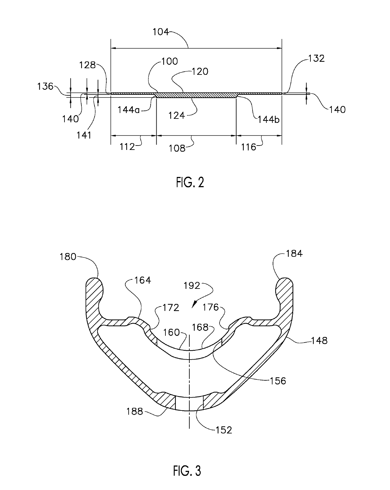
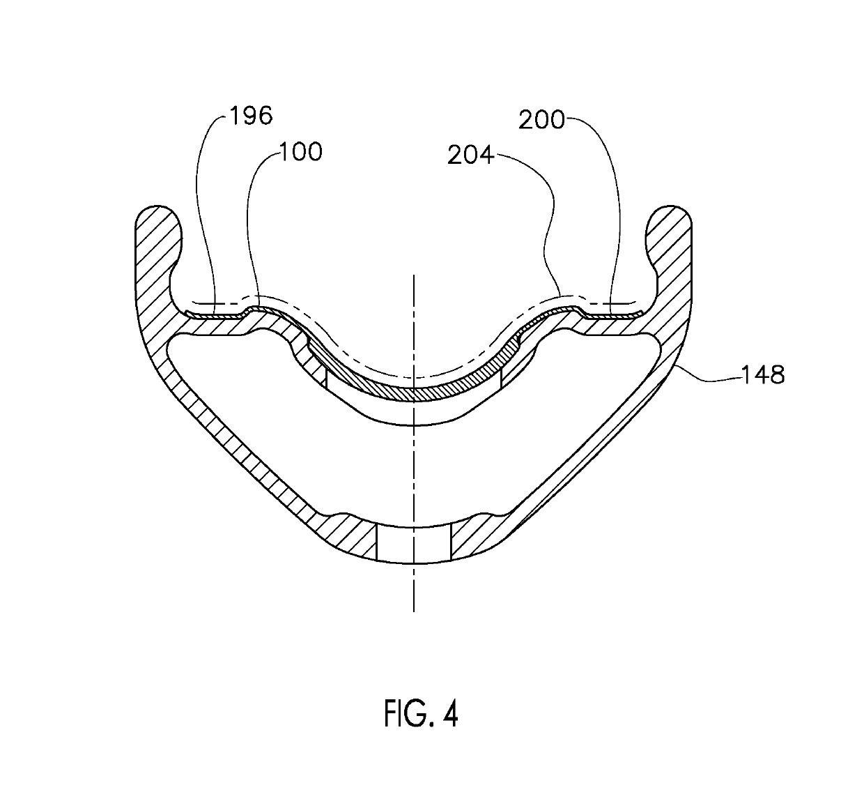
A rim sealing strip comprising: a circumferentially elongated rim strip having a radially outwardly facing outboard surface, a radially inwardly facing inboard surface, a first lateral edge and a second lateral edge laterally spaced from the first lateral edge; where the rim strip includes an overall lateral width between the first lateral edge and the second lateral edge and a radial thickness between the outboard surface and the inboard surface; and where the radial thickness is variable across the lateral width to include a first
lateral region having a first radial thickness and a second
lateral region having a second radial thickness, where the first radial thickness is thicker than the second radial thickness. A rim sealing
system comprising: a circumferentially elongated rim strip having a radially outwardly facing outboard surface, a radially inwardly facing inboard surface, a first lateral edge and a second lateral edge laterally spaced from the first lateral edge; a rim to receive the circumferentially elongated rim strip, where the rim includes a radially outwardly projecting first bead
flange, a radially outwardly projecting second bead
flange laterally spaced from the first bead
flange, and a radially outwardly facing tire
bed surface positioned laterally between the first bead flange and the second bead flange, and where the inboard surface of the rim strip circumscribes the tire
bed surface; where the rim strip includes an overall lateral width between the first lateral edge and the second lateral edge and a radial thickness between the outboard surface and the inboard surface; and where the radial thickness is variable across the lateral width to include a first
lateral region having a first radial thickness and a second lateral region having a second radial thickness, where the first radial thickness is thicker than the second radial thickness. A rim sealing strip comprising: a circumferentially elongated rim strip having a radially outwardly facing outboard surface, a radially inwardly facing inboard surface, a first lateral edge and a second lateral edge laterally spaced from the first lateral edge; where the rim strip includes an overall lateral width between the first lateral edge and the second lateral edge and a radial thickness between the outboard surface and the inboard surface; and where the rim strip includes a first lateral region and a second lateral region laterally adjoining the first lateral region; and where the material stiffness of the first lateral region has greater stiffness than the material stiffness of the second lateral region. A rim comprising: a rim, the rim comprising: a radially outwardly facing tire
bed surface along a circumference of the rim; and channel laterally positioned generally in the center of the tire bed surface and along the entire circumference; where the tire bed surface includes an unsealed opening there through to communicate to the
atmosphere; and where the channel has a lateral width that completely laterally overlaps the opening. A rim
system comprising: a rim, the rim comprising: a tire bed surface along a circumference of the rim; a channel generally in the center of the inner surface and generally along the entire circumference; a rim strip configured to be removeably seated in the channel; and rim tape configured to adhere to the tire bed surface and the rim strip. An
air barrier for a tubeless rim, the
air barrier comprising: a rim strip configured to be removeably seated in a center channel located on a tire bed surface along a circumference of a tubeless rim; and rim tape configured to adhere to the inner surface and the rim strip. A rim sealing strip comprising: a circumferentially elongated rim strip having a radially outwardly facing outboard surface, a radially inwardly facing inboard surface, a first lateral edge and a second lateral edge laterally spaced from the first lateral edge; where the rim strip includes an overall lateral width between the first lateral edge and the second lateral edge and a radial thickness between the outboard surface and the inboard surface; and where the rim strip includes a first lateral region and a second lateral region laterally adjoining the first lateral region; and where at least one of: (i) the radial thickness is variable across the lateral width to include a first lateral region having a first radial thickness and a second lateral region having a second radial thickness, where the first radial thickness is thicker than the second radial thickness; and (ii) the material stiffness of the first lateral region is greater than the material stiffness of the second lateral region.

