Water-collecting boundary block

Active Publication Date: 2019-07-25
MYS TECH
View PDF25 Cites 0 Cited by
  • Summary
  • Abstract
  • Description
  • Claims
  • Application Information

AI Technical Summary

Benefits of technology

[0023]According to the water collecting boundary block according to the present invention, since rainwater is collected into a body through a grating, collecting efficiency may be improved.
[0024]In addition, since water stored in the space portion is continuously supplied to ground through the drain part, the water collecting boundary block may prevent desertification in urban areas and death of a tree.
[0025]In addition, according to the water collecting boundary block according to the present invention, amount of water supplied to the ground through the drain part can be adjusted.
[0026]In addition, according to the water collecting boundary block according to the present invention, water ca

Problems solved by technology

At this time, since the roots of the trees are grown together with the trees, so that the roots infiltrate the sidewalk blocks or the roads, and the roots and the sidewalk blocks or roads of the trees are damaged.
As a result, there are problems that the management of the tree is costly, the safety accident

Method used


Image

  • Water-collecting boundary block
  • Water-collecting boundary block
  • Water-collecting boundary block

Examples


first embodiment

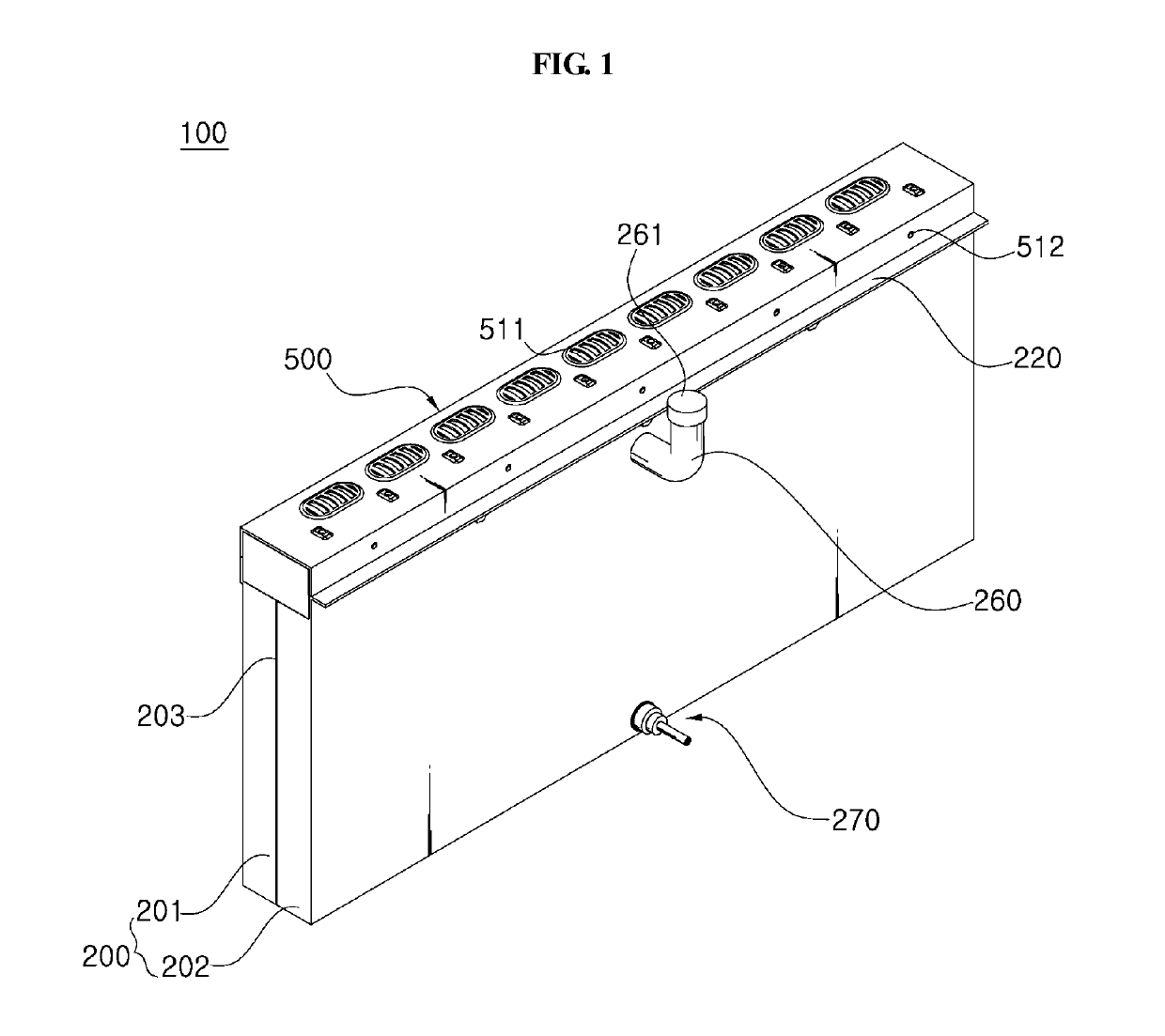
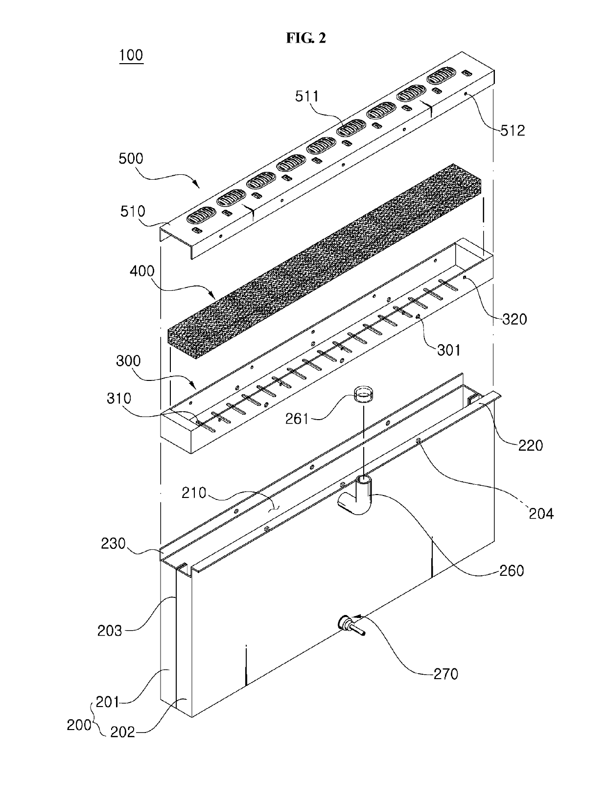
[0039]FIG. 1 is a perspective view of a water collecting boundary block according to a first embodiment of the present invention. FIG. 2 is an exploded perspective view of FIG. 1.

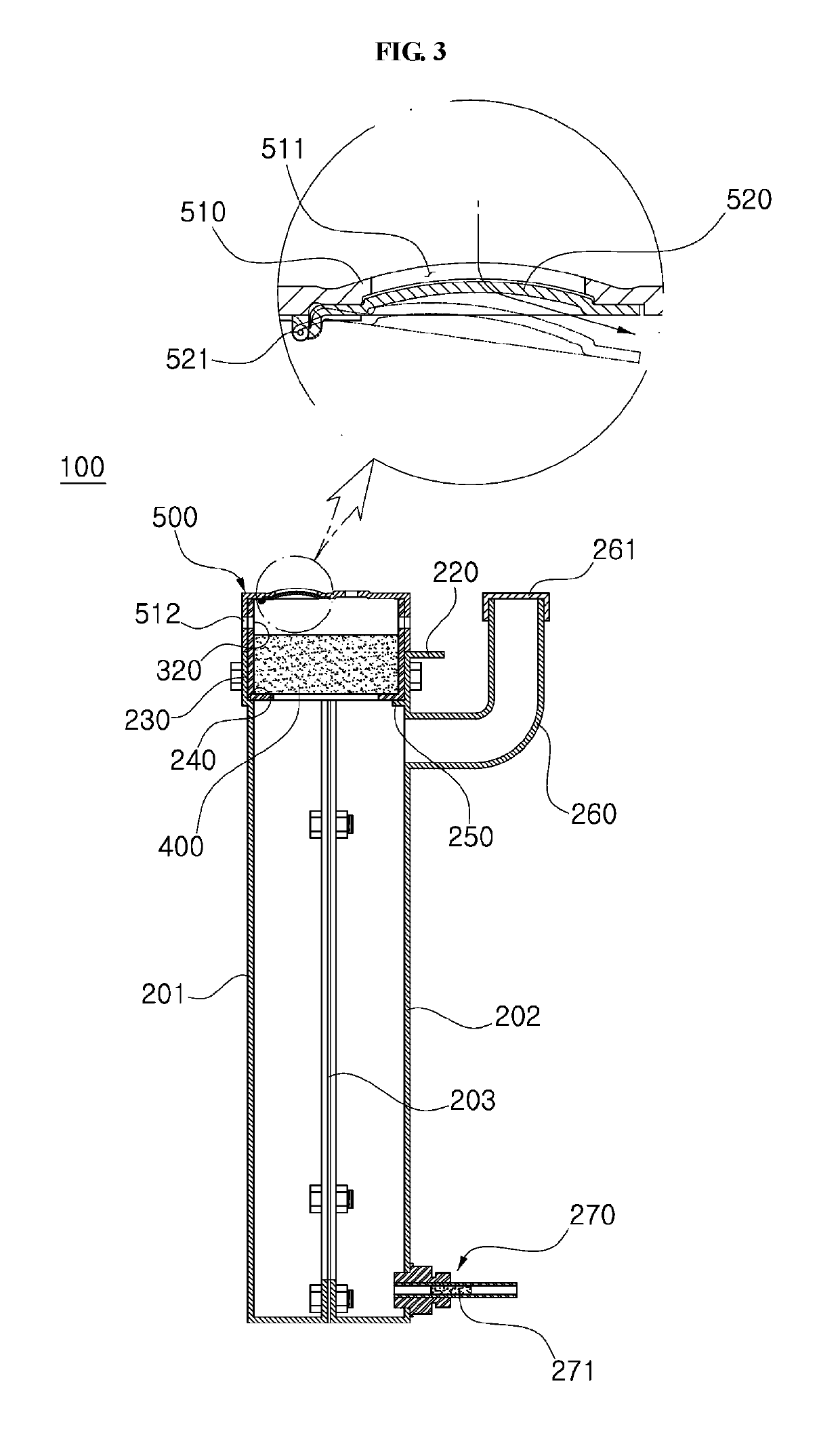
[0040]Referring to FIGS. 1 to 3, the water collecting boundary block 100 according to the first embodiment of the present invention includes a body 200 in which a space portion 210 is formed to store rainwater, a grating 500 seated on an upper portion of the body 200, and a drain part 270 formed at one side of a lower end of the body 200 for supplying water into the ground.

[0041]Here, the body 200 and the grating 500 may be made of a metal material such as aluminum or stainless steel which does not easily rust.

[0042]The body 200 may be formed in a box shape of a hexahedron having an opened top. For example, the body 200 may be formed in a form of a cube shape having a length longer than a width. Inside the body 200, a space portion 210 in which water introduced from outside can be stored is formed. Urethane...

second embodiment

[0062]FIG. 5 is an exploded perspective view of a water collecting boundary block according to a second embodiment of the present invention.

[0063]The water collecting boundary block 100a according to the second embodiment of the present invention is different from the first embodiment described above that there is no separate filter container 300, an inserting protrusion 221a at an upper end of the body 200a is inserted into a inserting groove 515a at a lower end of the grating 500a, and a mesh net 310a and a nonwoven filter 320a are interposed between the body 200a and the grating 500a

[0064]Therefore, the same reference numerals are assigned to the same elements as those of the above-described first embodiment, and a duplicate description thereof will be omitted. The second embodiment of the present invention will be described in detail, hereinafter.

[0065]According to the second embodiment of the present invention, the body 200a is formed with a seating portion 220a which is inwar...

third embodiment

[0073]FIG. 6 is a perspective view of a water collecting boundary block according to a third embodiment of the present invention. Hereinafter, the same reference numerals are assigned to the same elements having the same functions as those of the above-described embodiment, and redundant description will be omitted.

[0074]According to the third embodiment of the present invention, by connecting a plurality of water collecting boundary blocks 100b in series or in parallel, when the amount of water flowing into any one water collecting boundary block 100b exceeds the storage capacity, the water can be flow to other water collecting boundary blocks and stored therein.

[0075]For this, in the water collecting boundary block 100b according to the third embodiment of the present invention, a connecting port 281b connected to the space portions 210 and 210a is formed at an upper end of one side of the bodies 200 and 200a in the length direction, and a connecting hole 282b is formed in an uppe...


PUM


Abstract

A water collecting boundary block includes a body having an opened upper portion and a space portion formed therein, a grating which is seated on the body, and through which a plurality of rainwater inlets are formed, and a drain part formed at one side of a lower end of the body so as to be connected to the space portion, to provide water stored in the space portion to a ground.

Description

TECHNICAL FIELD[0001]Exemplary embodiments of the inventive concept relate to a water collecting boundary block. More particularly, exemplary embodiments of the inventive concept relate to a water collecting boundary block capable of effective rainwater management and controlling of the growth of roadside roots.BACKGROUND ART[0002]A rainwater collecting system installed for rapid drainage of rainwater includes a collecting well and a drainage line. In the rainwater collecting system, the collecting well provided on a side of the road is connected to a sewage main pipe on a lower side, and the drainage line is provided on an upper side, so that rainwater flows along the drainage line, flows naturally into the collecting well, and flows into the sewage main pipe.[0003]Upper parts of the collecting well and drainage line of the system of the rainwater collecting system is generally finished by grating so that people can safely pass through while passing rainwater through them. At this ...

Claims


Application Information

Patent Timeline
IPC IPC(8): E01C11/22E03F1/00E03F5/06
CPCE01C11/223E03F1/002E03F5/06E03F5/04E03F1/005E01C9/005E01C11/227E03F5/0401E01C11/224E03F1/00E01C11/22
Inventor KIM, JIN HWAN
Owner MYS TECH
Why Eureka
Try Eureka