Control device

Active Publication Date: 2019-07-25
SIMON SA
View PDF0 Cites 6 Cited by
  • Summary
  • Abstract
  • Description
  • Claims
  • Application Information

AI Technical Summary

Benefits of technology

[0024]Thus, the present disclosure enables using the entirety of the surface of the interface both for adjusting the light intensity and for turning the light fitting on and off, integrating a functional portion like the antenna of the communication module and the sensors in an

Problems solved by technology

Even though these devices function correctly, they penalize the control of the light intensity level compared to the turning on and turning off function, such that the user intuitively uses the device as a simple switching wit

Method used


Image

  • Control device

Examples


Embodiment Construction

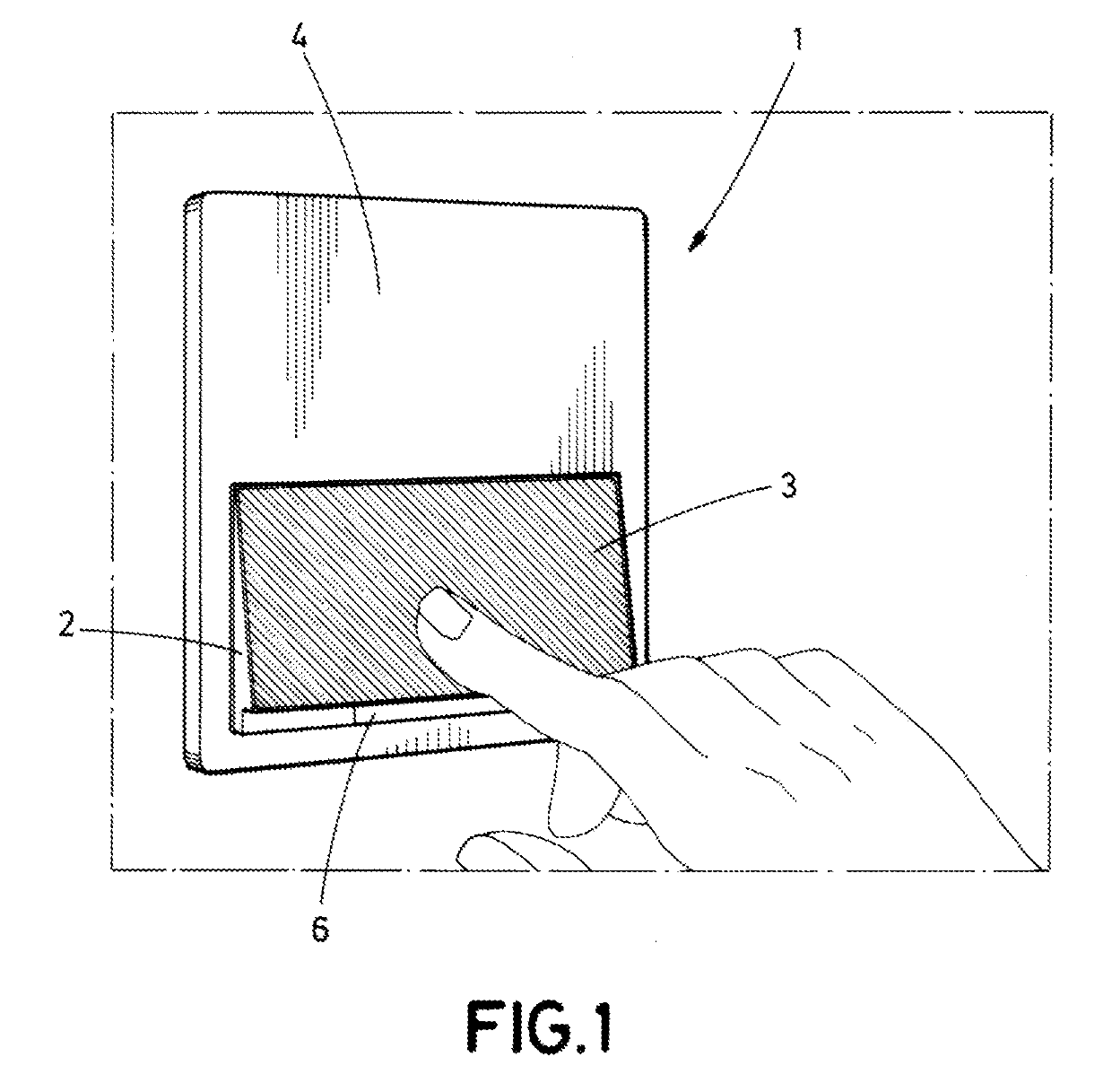
[0028]The present disclosure, as shown in FIG. 1, relates to a controlling device (1) for controlling a lighting system, not shown, comprising at least one light fitting, wherein said controlling device (1) is linked with said lighting system and comprises:[0029]a switching mechanism, not shown, linked to the lighting system and intended to turn the lighting system on and off.[0030]an adjusting mechanism comprising a control unit and is intended to adjust the light intensity of the light fitting, and[0031]an interface, by way of actuation surface of a rocker key (2) preferably surrounded by a frame (4), linked to a switching mechanism and to an adjusting mechanism, able to be actuated by a user in order to control the turning on and off, as well as adjusting the intensity of the lighting.

[0032]The switching mechanism comprises a switch with two states that enables, according to the open or closed state thereof, the electrical powering of the lighting. More specifically, the switch i...


PUM


Abstract

Controlling device for controlling a lighting system including at least one light fitting, where said controlling device is linked to said lighting system, and where the controlling device includes a switching mechanism intended to turn on and turn off the lighting system, an adjusting mechanism intended to adjust the light intensity of the lighting system, and an interface, able to be actuated by a user in order to control the turning on and turning off, as well as adjust the light intensity.

Description

TECHNICAL FIELD[0001]The disclosure concerns a controlling device for the turning on, turning off and adjustment of the light intensity of a lighting system comprising at least one light fitting.BACKGROUND[0002]Currently, controlling devices are known that use an adjusting button connected to a potentiometer for controlling the light intensity level of a light fitting. Thus, a user can adjust the level of lighting by rotating said button. This button can be pressed by a user to turn on or turn off said light fitting. Additionally, this controlling device can have a control unit that can comprise memorized light levels.[0003]Even though these devices function correctly, they penalize the control of the light intensity level compared to the turning on and turning off function, such that the user intuitively uses the device as a simple switching without using the light intensity control function.[0004]Furthermore, these devices from the state of the art do not adjust and indicate the l...

Claims


Application Information

Patent Timeline
IPC IPC(8): F21V23/04H01H23/00H01H23/24H01H23/02H05B37/02
CPCF21V23/0485H01H23/006H01H23/24H01H23/025H05B37/0209H05B37/0272H01H2239/006H01H2231/052H01H3/0213H01H23/143H05B47/10H05B47/165H05B47/19H03K17/955H03K2217/9607H01H23/14
Inventor RIQU REBULL, ADRIABATISTE MAYAS, CLARAPLAJA MIRO, SALVIGRAGERA GIL, MIGUELD AZ GONZ LEZ, SUSANA
Owner SIMON SA
Why Eureka
Try Eureka