Air conditioning system

Active Publication Date: 2019-08-01
SHINWA CONTROLS
View PDF8 Cites 0 Cited by
  • Summary
  • Abstract
  • Description
  • Claims
  • Application Information

AI Technical Summary

Problems solved by technology

Because of this system structure, the conventional air conditioning system disclosed in JP5886463B1 could not be sufficiently downsized as a whole.
In particular

Method used


Image

  • Air conditioning system
  • Air conditioning system
  • Air conditioning system

Examples


Embodiment Construction

[0021]Herebelow, one embodiment of the present invention is described. In the drawings attached to this specification, a scale size and an aspect ratio may be changed and exaggerated from the actual one, for the convenience of easiness in illustration and understanding.

[0022]In addition, terms specifying shapes, geometric conditions and their degrees, e.g., terms such as “parallel”, “perpendicular”, “same”, etc. and values of a length and an angle, etc., are not limited to their strict definitions, but should be construed to include a range capable of exerting a similar function.

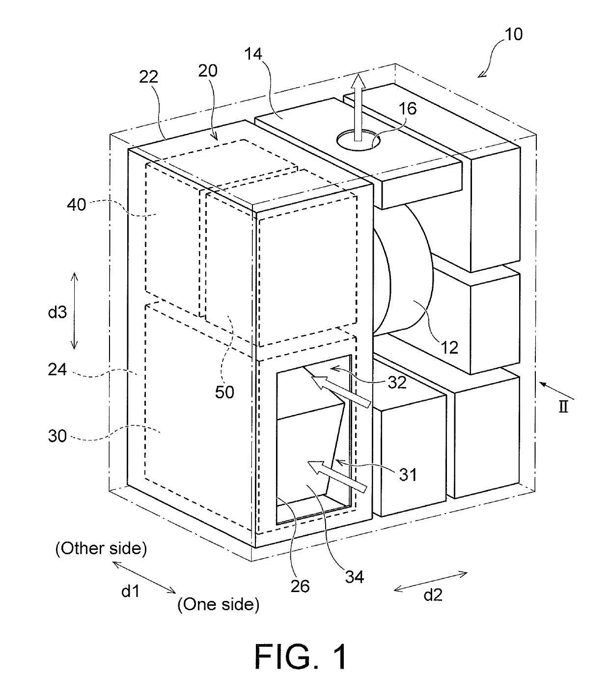
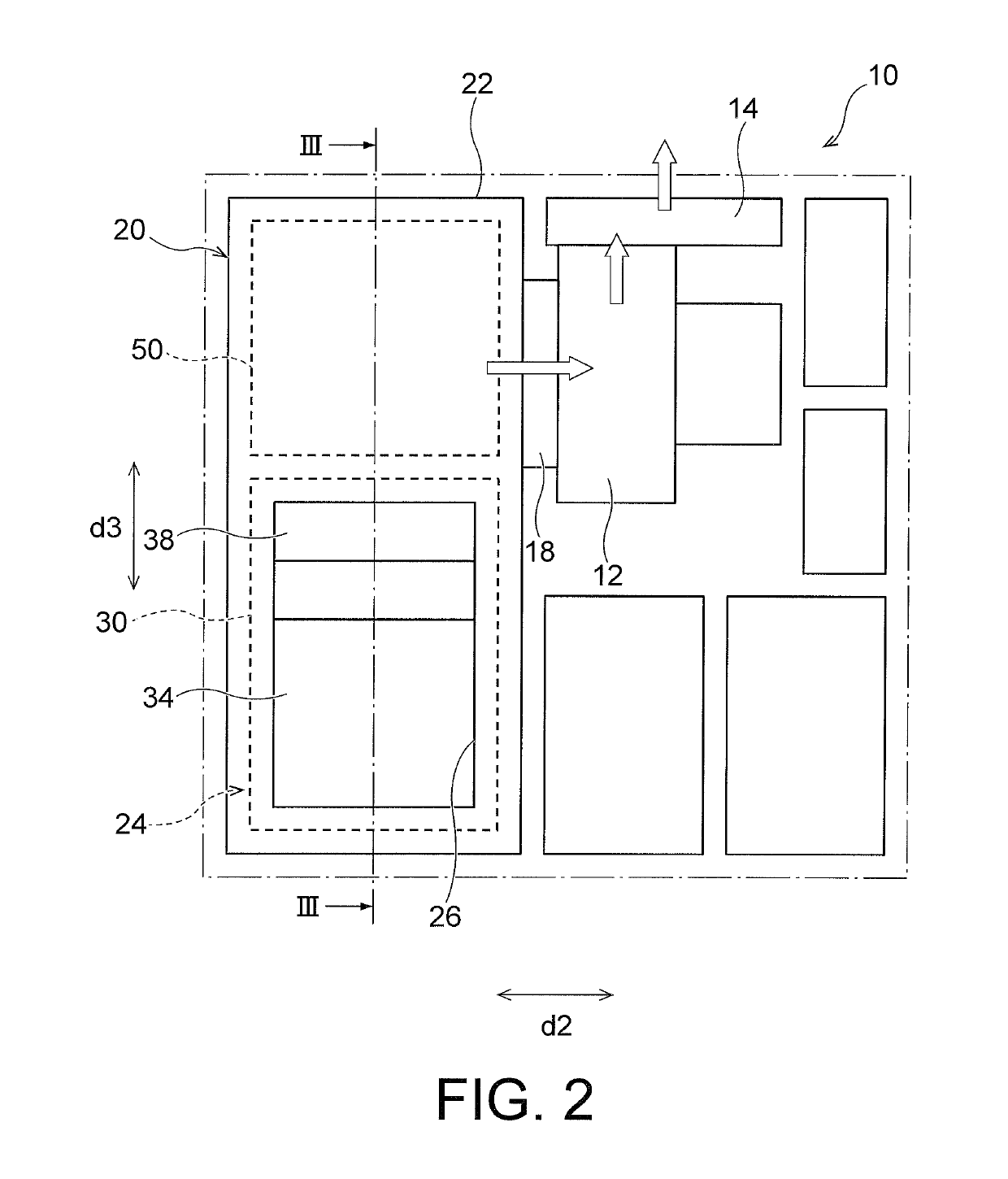
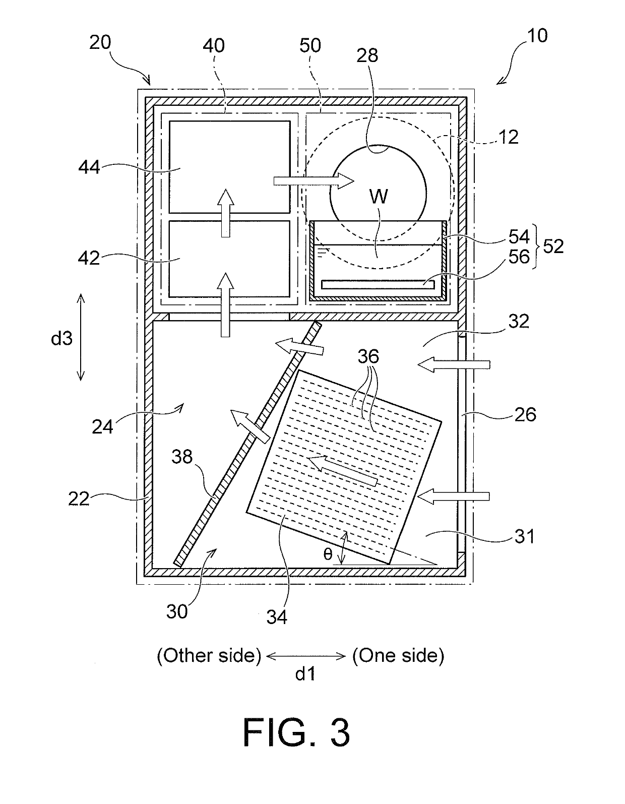
[0023]FIGS. 1 to 4 are views for describing one embodiment according to the present invention. FIG. 1 is a perspective view schematically showing an example of an air conditioning system 10. FIG. 2 is a view of the air conditioning system 10 of FIG. 1 seen from a direction of an arrow II. FIG. 3 is a sectional view corresponding to a III-III line of FIG. 2. FIG. 4 is a view showing the air conditioning syste...


PUM


Abstract

A downsized air conditioning system including a cooling device that cools air introduced into the air conditioning system to condense moisture contained in the air; a heating device that heats the air; and a humidification device that humidifies the air; wherein: in a plan view of the air conditioning system, at least a part of the humidification device is overlapped with at least a part of the cooling device; the heating device includes first and second heating devices, and in a plan view, at least a part of the first heating device and at least a part of the second heating device are respectively overlapped with at least a part of the cooling device; and when seen along an introduction direction of the air into the air conditioning system, at least a part of the humidification device is overlapped with at least a part of the heating device.

Description

TECHNICAL FIELD[0001]The present invention relates to an air conditioning system.BACKGROUND ART[0002]In a manufacturing step of semiconductor devices, an air conditioning system has been conventionally used for precisely control a temperature and a humidity of atmospheric air. For example, JP5886463B1 discloses an air conditioning system comprising a cooling unit that cools and dehumidifies air introduced into the air conditioning system, a heating unit that heats the air having passed through the cooling unit up to a predetermined temperature, and a humidification device that humidifies the air having passed through the heating unit.[0003]The air conditioning system is required to be further downsized in order to enable installation thereof in a narrow space, and to improve a degree of freedom of a location where it is installed.[0004]In the conventional air conditioning system disclosed in JP5886463B1, the air, which has moved upward to pass through the cooling unit so as to be co...

Claims


Application Information

Patent Timeline
IPC IPC(8): F24F13/30F24F3/14F24F6/10
CPCF24F13/30F24F3/14F24F6/10F24F11/0008F24F3/167F24F2221/34
Inventor ISHIMATSU, TAKUYA
Owner SHINWA CONTROLS
Why Eureka
Try Eureka