a gas turbine engine

A technology of gas turbines and turbines, which is applied in the field of turbines and can solve problems such as poor aerodynamic performance of turbines, complicated connection of turbine disks at all levels, and large changes in the inner diameter of rotor turbine disks.

Active Publication Date: 2016-06-15
HARBIN TURBINE +1
View PDF6 Cites 0 Cited by
  • Summary
  • Abstract
  • Description
  • Claims
  • Application Information

AI Technical Summary

Problems solved by technology

[0005] At present, the traditional turbine system has the following problems in product development and operation: ① F-class gas turbines with low and medium calorific value adopt a 3-stage turbine scheme. With the increase of turbine power, the gas flow required by the turbine increases , the turbine outlet area will increase, the expansion angle of the blade channel will increase a lot, and the aerodynamic performance of the turbine will be poor
②The structure of the moving impeller disc and the intermediate disc on the turbine rotor is compact. Due to the influence of the high-temperature gas in the channel, the distribution of cooling holes is reasonably arranged between the discs and the intermediate disc at all levels to facilitate the control of the cooling effect of the rotor and its components. As the flat power and number of turbine stages increase, the inner diameter of the rotor turbine disk changes greatly, and the connection of turbine disks at all stages is more complicated
The problems existing in the traditional turbine flow form and blade cooling system control technology will be more acute, and even completely unable to meet the requirements of the further development

Method used


Image

  • a gas turbine engine
  • a gas turbine engine
  • a gas turbine engine

Examples


Embodiment Construction

[0029] In order to make the object, technical solution and advantages of the present invention clearer, the present invention will be described in further detail below in conjunction with specific embodiments and with reference to the accompanying drawings.

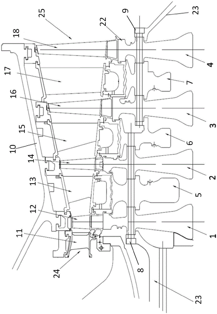
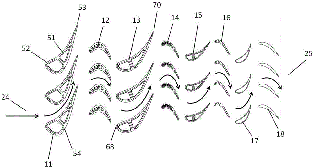
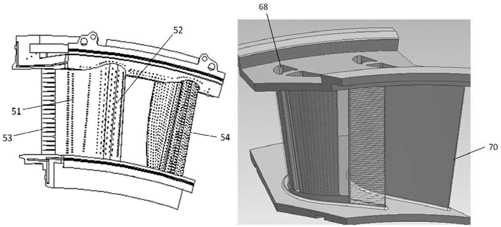
[0030] figure 1 is a cross-sectional view of the upper half of a turbine according to an embodiment of the present invention, such as figure 1 As shown, the turbine includes a casing 10, a turbine inlet 24, a turbine outlet 25, a turbine rotor 22, four-stage vanes 11, 13, 15 and 17, and four-stage moving blades 12, 14, 16 and 18, of which:

[0031] The turbine inlet 24 is located at one end of the turbine as an inlet for high-temperature gas;

[0032] The turbine outlet 25 is located at the other end of the turbine, as the outlet of high-temperature gas;

[0033] The stator blades of the four-stage vanes 11, 13, 15 and 17 are installed on the fixed casing 10 in sequence, and the moving blades of the four-stage rotor bl...


PUM


Abstract

The invention discloses a turbine motor of gas turbine; the turbine motor comprises a casing, a turbine motor entrance, a turbine motor exit, a turbine rotor, four-level fixed blades, and four-level movable blades. The turbine rotor comprises four impeller disks and three intermediate disks; the four impeller disks and the three intermediate disks are alternately arranged along an axial direction, and are connected together via a group of pull rods. The fixed blades are mounted on the fixed casing, and an impingement cooling sleeve is arranged therein, film holes are arranged on the surface thereof, and a convection cooling channel is arranged on the trailing edge thereof. The movable blades are mounted on one side of the rotor and revolve together with the rotor, wherein three levels are hollow structures, a double-snakelike cooling channel and multiple groups of herringbone fins are arranged therein. The fixed blades and the movable blades are alternately arranged in the axial direction of the rotor, and form a gas combustion channel therein. When the gas turbine is running, the turbine motor is able to effectively change the thermal energy of the high-temperature gas into the mechanical energy for rotating the rotor, and ensure the safety of the mechanical movement by sufficient and reasonable cooling.

Description

technical field [0001] The invention relates to a gas turbine turbine, in particular to a gas turbine turbine with equal-medium-diameter gas passages and four-stage turbine blades. Converted into mechanical energy of the rotor. Background technique [0002] Modern high-power gas turbines for power generation mainly use gaseous fuels, and their turbine systems generally adopt a multi-stage turbine scheme with cooling, that is, high-temperature gas is introduced from the outlet of the combustion chamber through the guide static cascade with cooling structure, and then introduced into the first-stage dynamic turbine. The blade releases part of the energy to do work. After the first-stage moving blades, a similar static cascade and moving blade cascade structures are arranged to convert the thermal energy of the high-temperature gas into mechanical energy step by step. [0003] According to the requirements of the whole machine for the working ability of the turbine, the therm...

Claims


Application Information

Patent Timeline
Patent Type & Authority Patents(China)
IPC IPC(8): F01D1/04F01D5/06F01D5/14F01D9/02F01D25/14F01D5/08F01D5/18
Inventor 张秋鸿张宏涛冯永志石玉文吕智强李振中赵俊明王思远王辉姜东坡席会杰张成义慕粉娟张文军
Owner HARBIN TURBINE
Why Eureka
Try Eureka