No-shaft magnetic pump

A magnetic pump and shaftless technology, which is applied in the direction of pumps, pump devices, pump components, etc., can solve the problems of complex shaft drive structure, inability to flexibly adjust, increase pump dissolution loss, etc., to meet the needs of high-power magnetic rotation, Cooling and lubricating direct and effective, widening the effect of technology development path

Active Publication Date: 2006-08-02
丹东克隆先锋泵业有限公司
View PDF0 Cites 4 Cited by
  • Summary
  • Abstract
  • Description
  • Claims
  • Application Information

AI Technical Summary

Problems solved by technology

The main technical problems existing in the existing magnetic pumps are: the shaft drive structure is complex, resulting in a large pump volume, and at the same time, part of the pumping medium needs to be drawn from the pumping high-pressure area to cool the spacer sleeve and lubricate the bearings, which not only increases the cost of the pump. Dissolution loss reduces the pump efficiency, and because the cooling channel is long, the cooling effect is difficult to meet the actual work needs, and it cannot be adjusted flexibly, so the power matching of the pump is greatly restricted, and it has become a technology for the development of high-power magnetic pumps. bottleneck

Method used


Image

  • No-shaft magnetic pump

Examples


Embodiment Construction

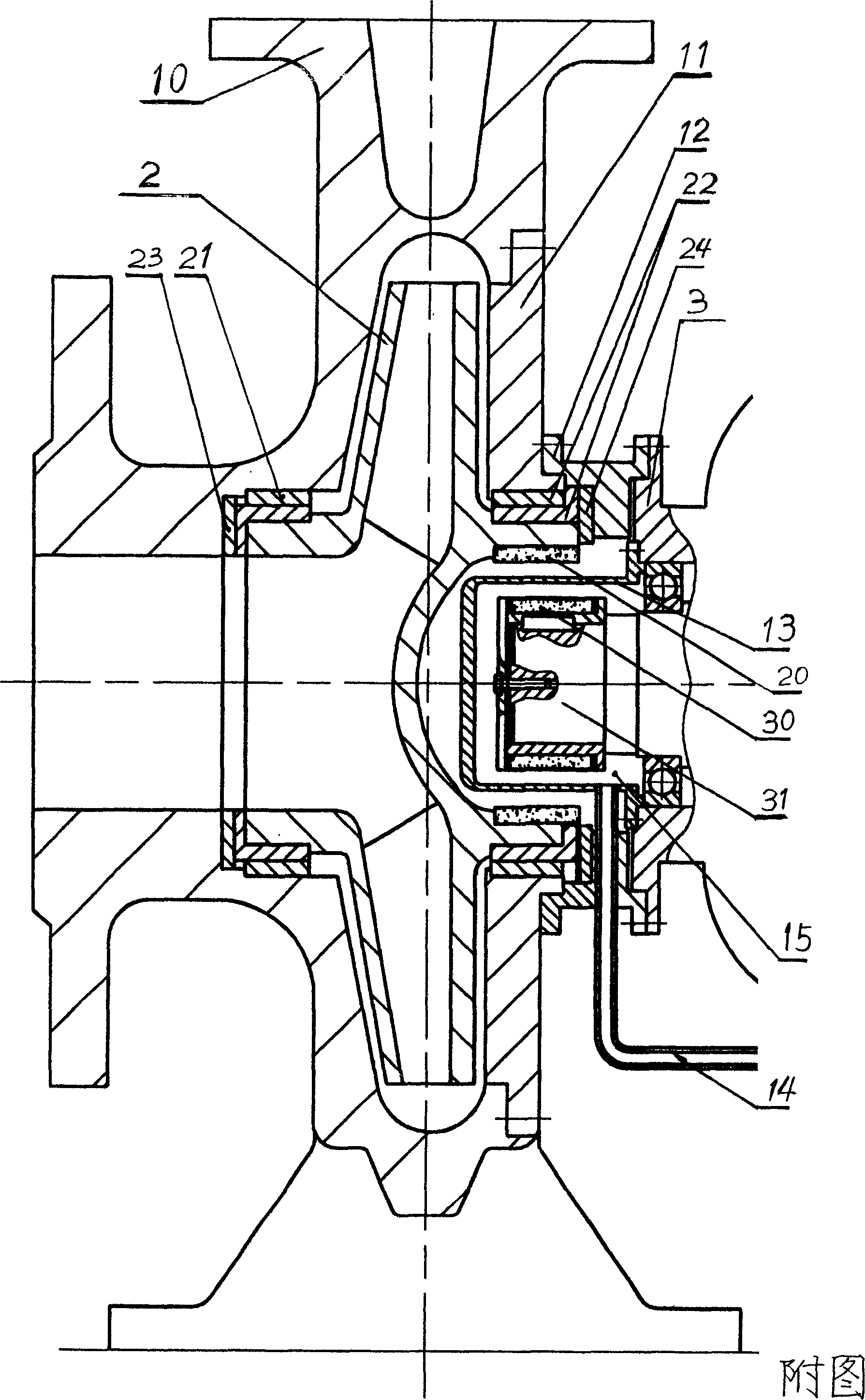
[0006] The structure of the shaftless magnetic pump of the present invention is shown in the figure, and its pump impeller 2 is assembled on the pump inlet of the pump body 10 and the side opposite to the pump inlet through the sliding bearings at both ends of the pump impeller 21, 22 and the thrust discs 23 and 24. On the pump cover 11, the drive matching end of the pump impeller 2 and the motor output shaft 31 is set as an outer magnetic rotor 20, and the motor output shaft 31 is fixedly equipped with an inner magnetic sleeve 30, so that it constitutes an inner magnet that is magnetically matched with the outer magnetic rotor 20 of the pump impeller. The magnetic rotor, the motor 3 is fixedly assembled on the pump cover 11 and the pump body 10 through the coupling frame 12, driven by the motor 3, the pump impeller 2 is driven to rotate at high speed under the action of magnetic force to realize pumping. The space between the two magnetic rotors is provided with a spacer 13, w...


PUM


Abstract

The present invention is one technological scheme of no-shaft magnetic pump with the pump vane wheel and the motor output shaft as the magnetically driven rotors and isolating sleeve to close the motor and the pumping space. The technological scheme has greatly simplified pump structure, greatly reduced volume loss and obviously raised pumping efficiency, and the closed isolating sleeve creates condition for reinforcing the cooling design.

Description

technical field [0001] The present invention relates to a magnetic drive pump, in particular to an improvement technique for its pump power. Background technique [0002] In the existing magnetic pump, the pump shaft drive part is driven by the output shaft of the motor through the linkage shaft and the magnetic drive part to drive the driven shaft, that is, the pump shaft, to generate pumping drive. The magnetic drive part is set on the outer rotor of the linkage shaft and the inner rotor of the pump shaft matched with it. A spacer sleeve is set between the outer rotor and the inner rotor. The spacer sleeve isolates the space of the pump shaft and the space of the linkage shaft and forms a A small portion of the pumped medium cools the cooling channels of the magnetic drive section. The main technical problems existing in the existing magnetic pumps are: the shaft drive structure is complex, resulting in a large pump volume, and at the same time, part of the pumping medium...

Claims


Application Information

Patent Timeline
Patent Type & Authority Applications(China)
IPC IPC(8): F04D13/06F04D29/58F04D29/06
Inventor 何若博周福兴
Owner 丹东克隆先锋泵业有限公司
Why Eureka
Try Eureka