

Vitreous silica crucible
A technology of glass crucible and silicon oxide, which is applied in glass forming, glass manufacturing equipment, chemical instruments and methods, etc., and can solve problems such as instability
- Summary
- Abstract
- Description
- Claims
- Application Information
AI Technical Summary
Problems solved by technology
Method used
Image

Examples
Embodiment 1
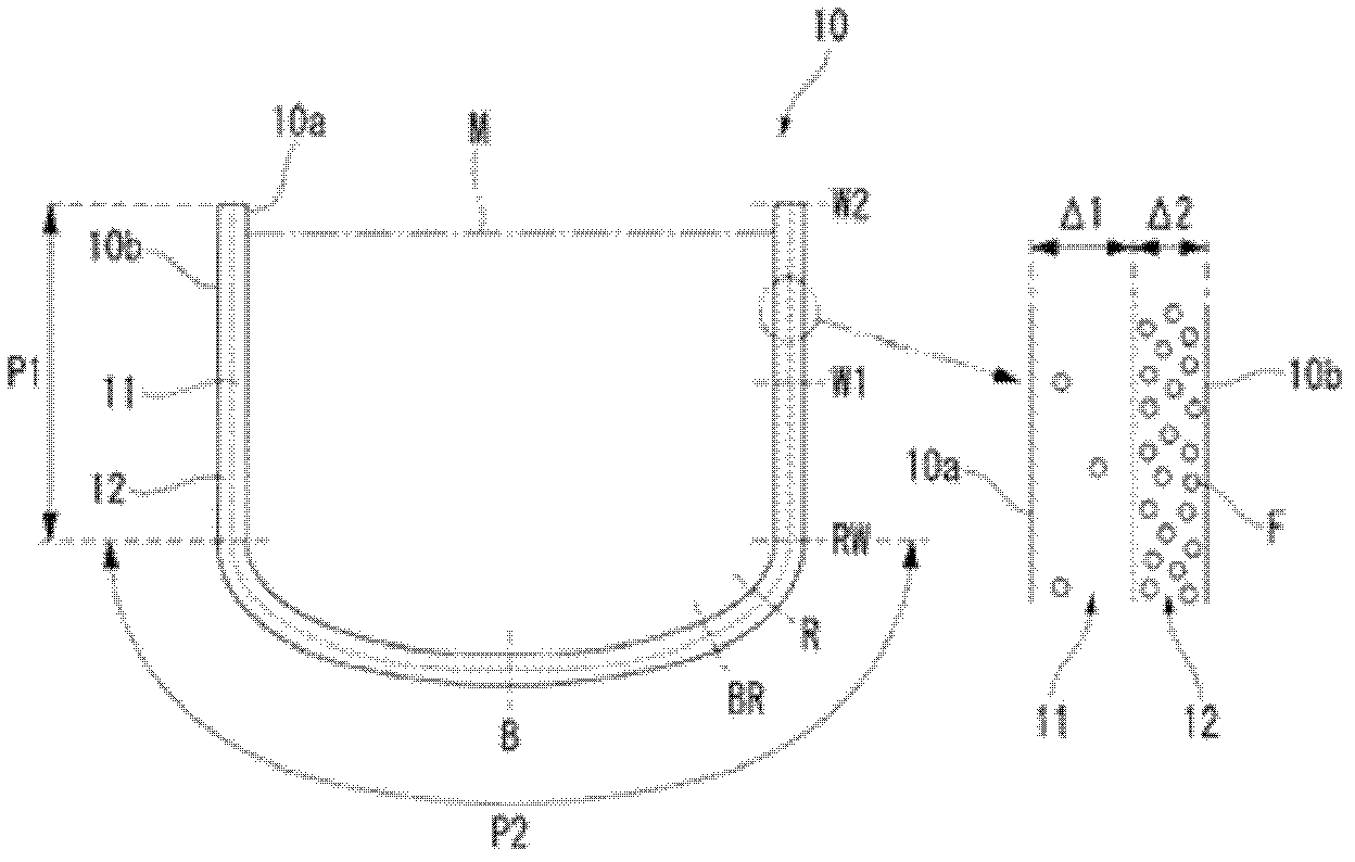
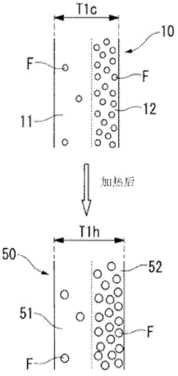
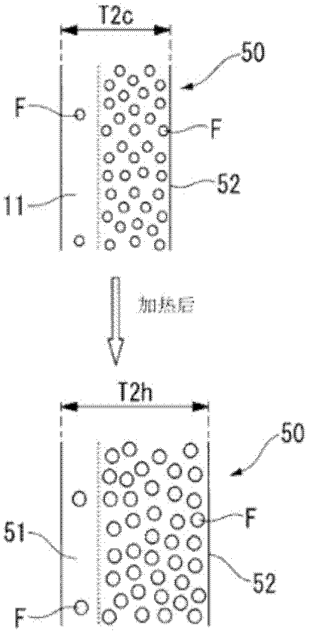
[0102] Examples related to the present invention are described below. First, cut out an actual vitreous silica crucible such as Figure 5 Samples of the shape shown. The sampling sites of each sample were figure 1 W2, W1, RW, R, BR, B sites shown. Here, parts W2 and W1 are the upper end and center of the cylindrical straight body, RW is the upper end of the corner, R is the middle part of the corner, BR is the boundary between the corner and the bottom, and B is the center of the bottom. In addition, in each graph showing the results, the sample of the transparent layer is represented by T, the sample of the bubble-containing layer is represented by F, and the double-layered sample of the transparent layer and the bubble-containing layer is represented by T+F. Regarding each of these samples, the volume expansion rate, specific gravity decrease, air bubble content rate, and the like were measured.
[0103] First, the volume expansion ratios of samples T, F, and T+F were m...
Embodiment 2
[0115]A vitreous silica crucible A of the present invention and a conventional vitreous silica crucible B (diameter 24 inches; 61 cm) were prepared. The thicknesses of the transparent layer and bubble-containing layer of vitreous silica crucibles A and B are shown in Table 1, respectively. The air bubble content of the transparent layer is about 0.005% at the center of the bottom, about 0.1% at the boundary between the bottom and the corner, and about 0.05% from the middle portion between the upper end and the lower end of the straight barrel to the upper end. The average diameter of the bubbles in the transparent layer was about 80 μm. In addition, the bubble content of the bubble-containing layer was about 0.5%, and the average diameter of the bubbles was about 150 μm.
[0116] 【Table 1】
[0117]
[0118] Then, for the vitreous silica crucible A and the vitreous silica crucible B, the parts W1, R, and B (refer to figure 1 ) volume expansion rate. The measurement resu...
Embodiment 3
[0120] Vitreous silica crucibles 1 to 5 having a transparent layer and a bubble-containing layer having the thickness shown in Table 2 were produced. The vitreous silica crucibles 3 and 5 correspond to the vitreous silica A and B of Example 2, respectively. The bubble content ratios of the transparent layer and the bubble-containing layer were the same as in Example 2. Using these vitreous silica crucibles, silicon single crystals were pulled, and the crystallinity of the obtained single crystals was evaluated. Crystallinity was evaluated based on the value (single crystal ratio) of (mass of straight cylindrical portion of single crystal silicon) / (mass of polycrystalline silicon filled in the crucible immediately before pulling). The results are shown in Table 2. The evaluation criteria in Table 2 are as follows.
[0121] ◎: Single crystal ratio 0.80 to less than 0.99
[0122] ○: Single crystal ratio 0.70 to less than 0.80
[0123] △: Single crystal ratio 0.60 to less tha...
PUM
| Property | Measurement | Unit |
|---|---|---|
| diameter | aaaaa | aaaaa |
| diameter | aaaaa | aaaaa |
| wavelength | aaaaa | aaaaa |
Abstract
Description
Claims
Application Information