Pump unit using magnetic driving core body

A technology of magnetic drive and pump unit, which is applied to parts, pump elements, pumps, etc. of pumping devices for elastic fluids, and can solve the problems of occupying space, high cost, and inconvenient use

Inactive Publication Date: 2006-11-29
刘 明华 +2
View PDF1 Cites 4 Cited by
  • Summary
  • Abstract
  • Description
  • Claims
  • Application Information

AI Technical Summary

Problems solved by technology

[0003] The aforementioned traditional pump device, in addition to having to be equipped with the motor, has the disadvantages of occupying space and high cost. On the other hand, a single pipeline system is usually equipped with a single pump

Method used


Image

  • Pump unit using magnetic driving core body
  • Pump unit using magnetic driving core body
  • Pump unit using magnetic driving core body

Examples


Embodiment Construction

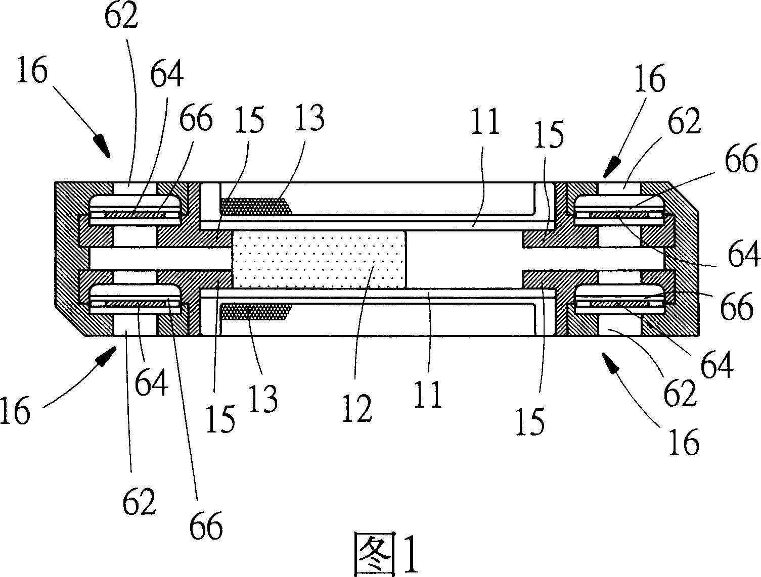
[0119] Please refer to FIG. 1 , the present invention discloses a pump unit that utilizes a magnetic force to drive a core, which at least includes a main body 11 , a core 12 , and a coil 13 .

[0120] The main body 11 has a length and has a chamber inside. For example, it can be set as a tube body. At least the outer side of the main body 11 is made of magnetically conductive materials such as silicon steel, iron, amorphous materials, permanent magnets or superconductors. The structure can be continuously wound in one piece to form a hollow circular tube body, and a hollow circular tube body can also be formed by several sleeves with different circular diameters being intertwined with each other.

[0121] The core 12 has a length and an outer edge shape corresponding to the shape of the inner edge of the container and is swingably disposed in the container, and can be a magnet or a superconductor under the action of a magnetic force.

[0122] The coil 13 is wound on the outsi...


PUM


Abstract

The invention relates a pump unit that driving a core identity by magnetic force. It includes an identity, a core identity, and a coil. A container is contained in the identity, and the outside is magnetic guiding material. The core identity has a certain length. And the inner margin shape could be set in the container. The coil is twisting outside the identity, and connecting to a circuit that supply current to coil to drive the core identity taking back and forth movement. The container connecting the hatch of the identity, and two single direction valve sections set the two ends of the identity to allow the liquid flow from the first location to the second location direction to achieve the function of driving the liquid.

Description

technical field [0001] The present invention relates to a pump device that pushes fluid flow, in particular to a pump unit that utilizes magnetic force to drive a core. Background technique [0002] The traditional pump device that pushes the fluid to flow in a pipeline mostly includes a water wheel device or a pump device connected to a pipeline, and then an external motor is used to link the water wheel device with the rotational motion of the motor. The rotary motion or the reciprocating motion of the pump device further pushes the fluid in the pipeline to circulate between the two places or transport the fluid from one place to another. [0003] In addition to the disadvantages of occupying space and high cost due to the need for the above-mentioned conventional pump device to be equipped with the motor, on the other hand, a single-pipeline system is usually equipped with a single-pump device, or a single-pump device can be combined with a two-pipe system, but However, ...

Claims


Application Information

Patent Timeline
IPC IPC(8): F04B17/04H02K33/18F04B53/10
Inventor 刘明华陈定福简金榜
Owner 刘 明华
Why Eureka
Try Eureka