Gas turbine inlet guide vane design method, gas turbine and aeroengine

A technology of imported guide vanes and gas turbines, which is applied in the field of aero-engines, can solve the problems of reducing the available gas volume for cooling and mixing in the combustion chamber, increasing the aerodynamic loss of the inlet guide vanes, and reducing the transmission efficiency of the turbine, so as to achieve reasonable distribution of aerodynamic parameters and aerodynamic The effect of less loss and reducing the amount of air-conditioning

Active Publication Date: 2022-12-02
AECC HUNAN AVIATION POWERPLANT RES INST
View PDF2 Cites 0 Cited by
  • Summary
  • Abstract
  • Description
  • Claims
  • Application Information

AI Technical Summary

Problems solved by technology

[0004] The invention provides a method for designing the inlet guide vane of a gas turbine, a gas turbine and an aeroengine, so as to solve the problem that the air flow of the inlet guide vane of the gas turbine in the existing aeroengine is too much and the aerodynamic loss of the inlet guide vane is increased. , reduces the transmission efficiency of the turbine, and correspondingly reduces the available gas volume for cooling and mixing in the combustion chamber; making a large number of air film holes on the blade body of the inlet guide vane will increase the difficulty of the process, making the technical problem of high manufacturing cost

Method used


Image

  • Gas turbine inlet guide vane design method, gas turbine and aeroengine
  • Gas turbine inlet guide vane design method, gas turbine and aeroengine
  • Gas turbine inlet guide vane design method, gas turbine and aeroengine

Examples


Embodiment Construction

[0029] The embodiments of the present invention will be described in detail below with reference to the accompanying drawings, but the present invention can be implemented in various ways defined and covered below.

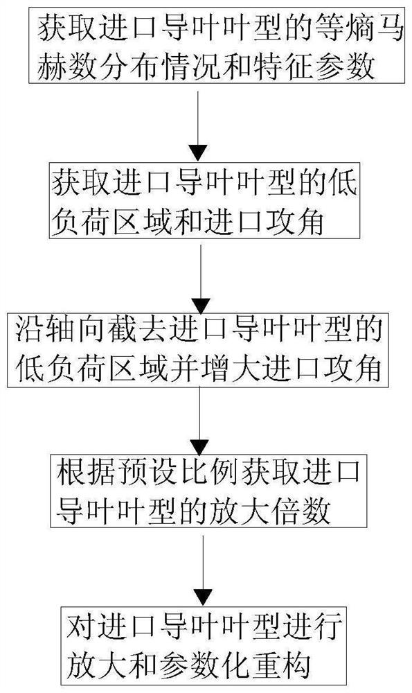
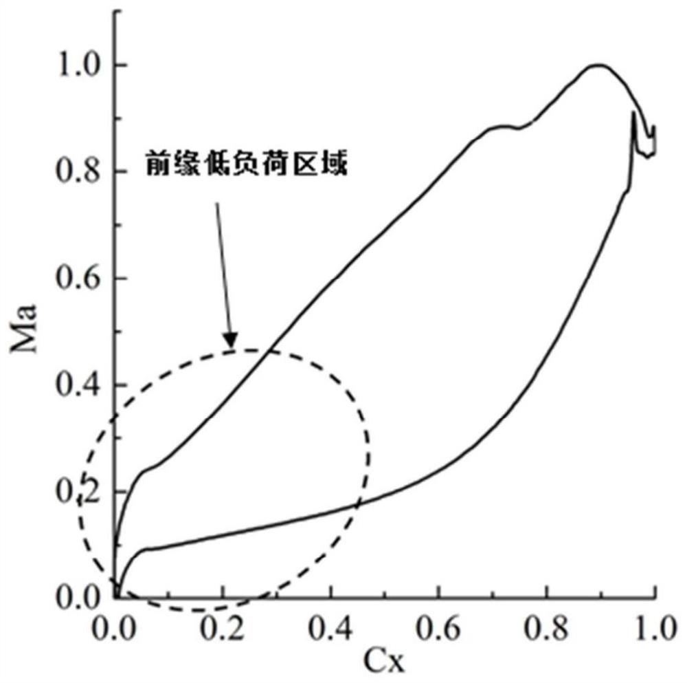
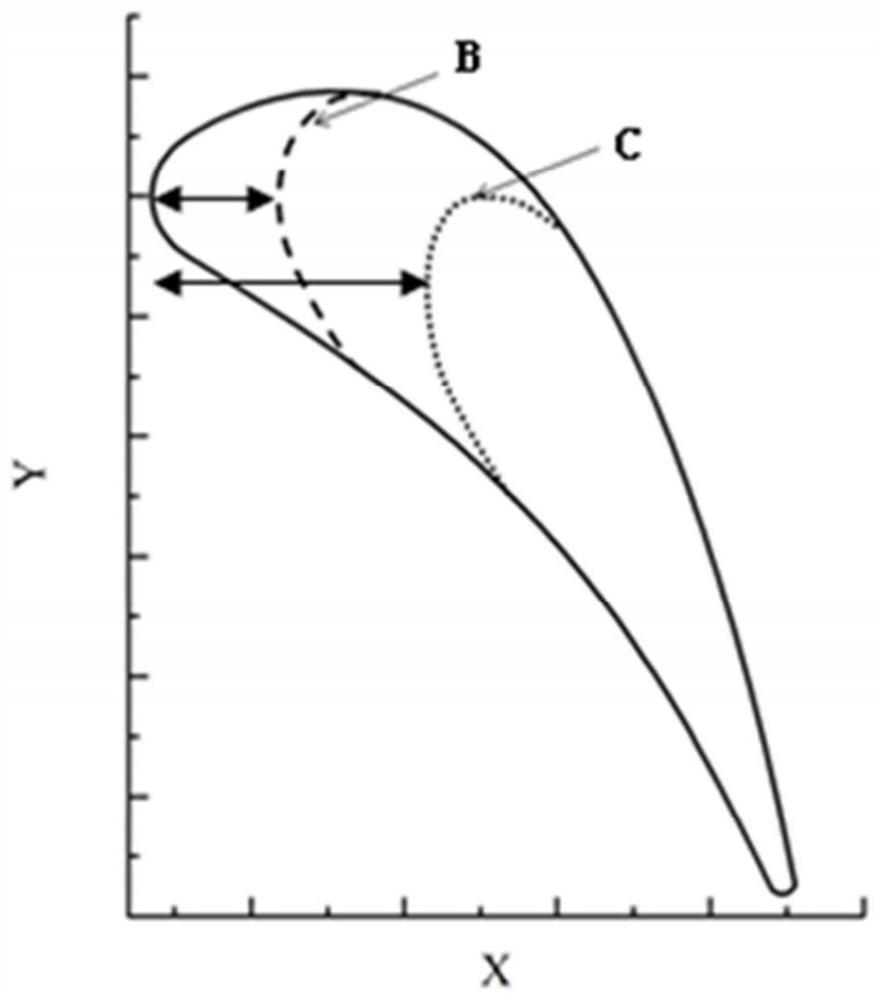
[0030] figure 1 It is a flow chart of the steps of the gas turbine inlet guide vane design method of the preferred embodiment of the present invention; figure 2 is the isentropic Mach number distribution diagram of the basic airfoil surface of the present invention; image 3 is a schematic diagram of step c in the gas turbine inlet guide vane profile design method of the preferred embodiment of the present invention; Figure 4 It is a comparative schematic diagram of the inlet guide vane types of the three schemes of the present invention; Figure 5 It is the comparison chart of the isentropic Mach number distribution on the inlet guide vane surface of the three schemes of the present invention; Image 6 It is the distribution comparison diagram of the total ...


PUM


Abstract

The invention discloses a method for designing the inlet guide vane profile of a gas turbine. The isentropic Mach number distribution and characteristic parameters of the inlet guide vane profile surface are acquired through simulation, and the low-load area and inlet attack of the inlet guide vane profile surface are obtained. Angle; cut off the low load area of ​​the leading edge of the inlet guide vane by cutting off the front edge to build a high load inlet guide vane, and increase the inlet angle of attack of the inlet guide vane to increase the inlet guide vane In order to keep the axial installation space of the blade in the aero-engine unchanged, the inlet guide vane profile is enlarged and the parameters are reconstructed, so that the distribution of aerodynamic parameters on the surface of the inlet guide vane is reasonable, the aerodynamic loss is small, and the inlet After the guide vane is enlarged, the blade grid pitch of the turbine is enlarged correspondingly, and the number of blades of the turbine is correspondingly reduced in proportion, thereby reducing the amount of cold air used for the inlet guide vane and reducing the manufacturing cost.

Description

technical field [0001] The invention relates to the technical field of design and processing of aero-engine parts, in particular to a design method of a gas turbine inlet guide vane profile. In addition, the present invention also relates to a gas turbine designed, processed and manufactured using the above-mentioned gas turbine inlet guide vane profile design method. In addition, the present invention also relates to an aeroengine comprising the above-mentioned gas turbine. Background technique [0002] In the existing small and medium-sized aviation gas turbine engines, the turbine is one of the core components of the gas turbine engine power plant. It is a turbomachinery that converts the energy of high-temperature and high-pressure gas into kinetic energy and mechanical energy. When the gas flows from the turbine inlet through the guide vane row, it turns and expands, and then converts the gas pressure potential energy into gas kinetic energy, so that the high-speed gas...

Claims


Application Information

Patent Timeline
Patent Type & Authority Patents(China)
IPC IPC(8): G06F30/15G06F30/17G06F30/20F01D9/02G06F119/20
CPCG06F30/15G06F30/17G06F30/20F01D9/02G06F2119/20Y02T90/00
Inventor 张绍文王政谭锋屈彬房兴龙
Owner AECC HUNAN AVIATION POWERPLANT RES INST
Why Eureka
Try Eureka