Device and method for obtaining distance information from views

a technology of distance information and view, applied in the field of digital image processing, can solve the problems of using four-dimensional gradients and, thus, more computationally expensive, and achieve the effects of smooth transitions, improved depth measurement precision, and high resolution

Active Publication Date: 2019-08-01
PHOTONIC SENSORS & ALGORITHMS SL
View PDF0 Cites 30 Cited by
  • Summary
  • Abstract
  • Description
  • Claims
  • Application Information

AI Technical Summary

Benefits of technology

[0041]According to an embodiment, the present invention refers to a device and method for real-time depth estimation using a multiview imaging system. The system comprises at least one light field plenoptic camera and can also include additional conventional cameras. Such a multiview system, with the appropriate image processing procedures, is able to create a depth map of the scene with a very high-quality resolution, overcoming the drawbacks of current plenoptic cameras and multi-camera systems. The present invention achieves better precision in depth measurements and in the maximum measurable depth, and at the same time also provides additional advantages s...

Problems solved by technology

Similar methods based on four-dimensional gradients (an...

Method used


Image

  • Device and method for obtaining distance information from views
  • Device and method for obtaining distance information from views
  • Device and method for obtaining distance information from views

Examples


Embodiment Construction

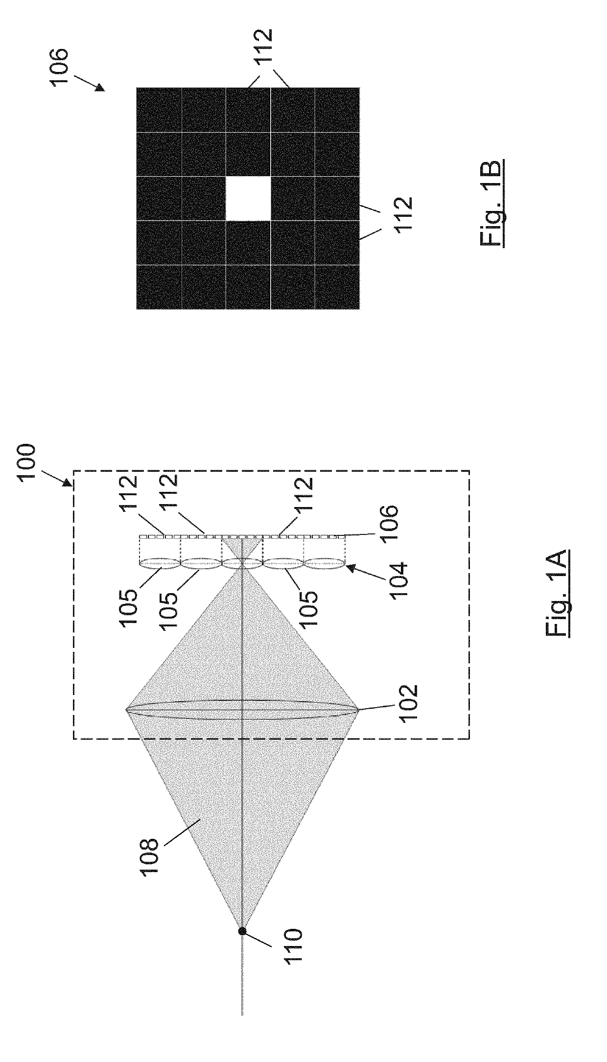
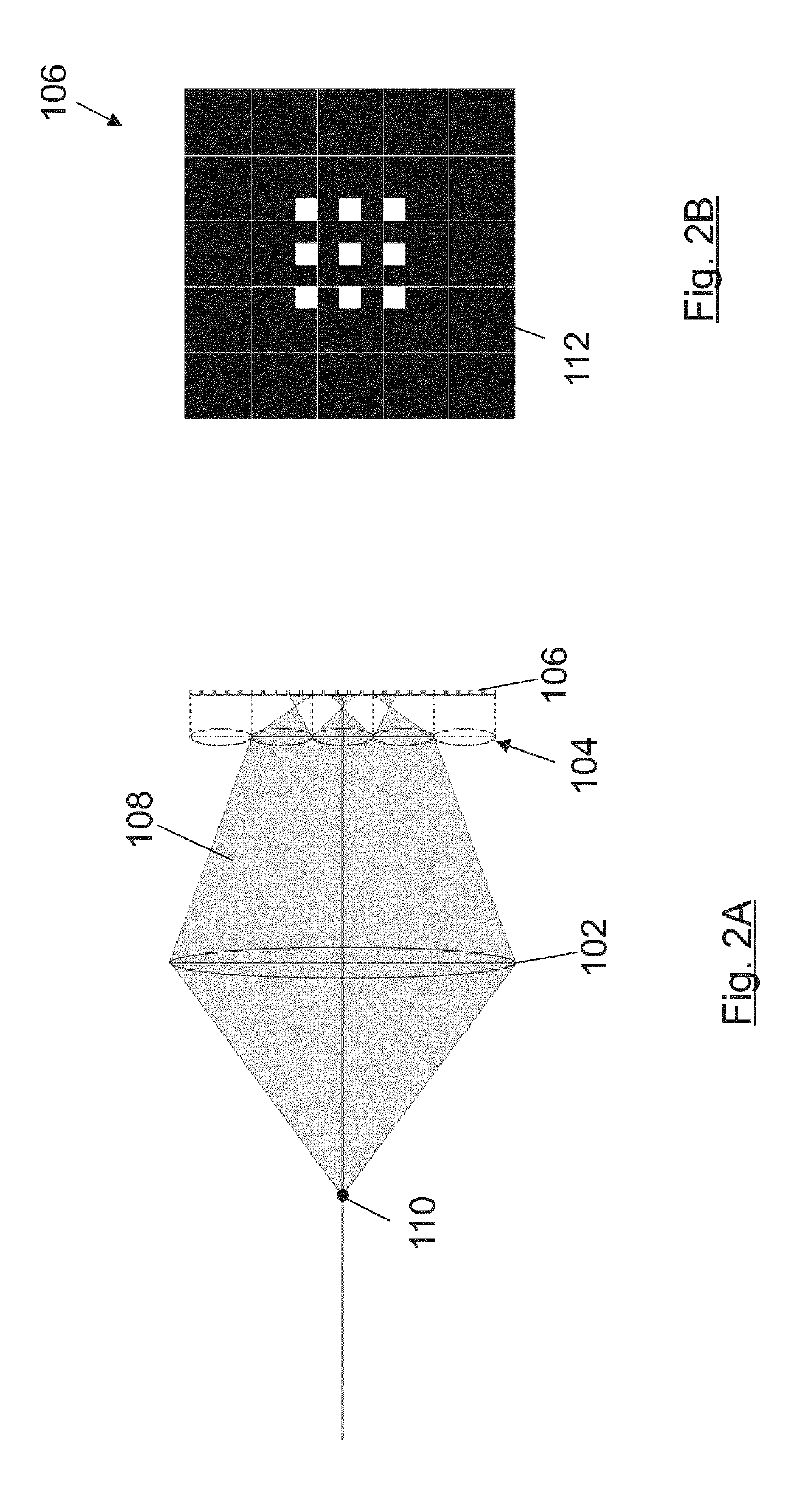
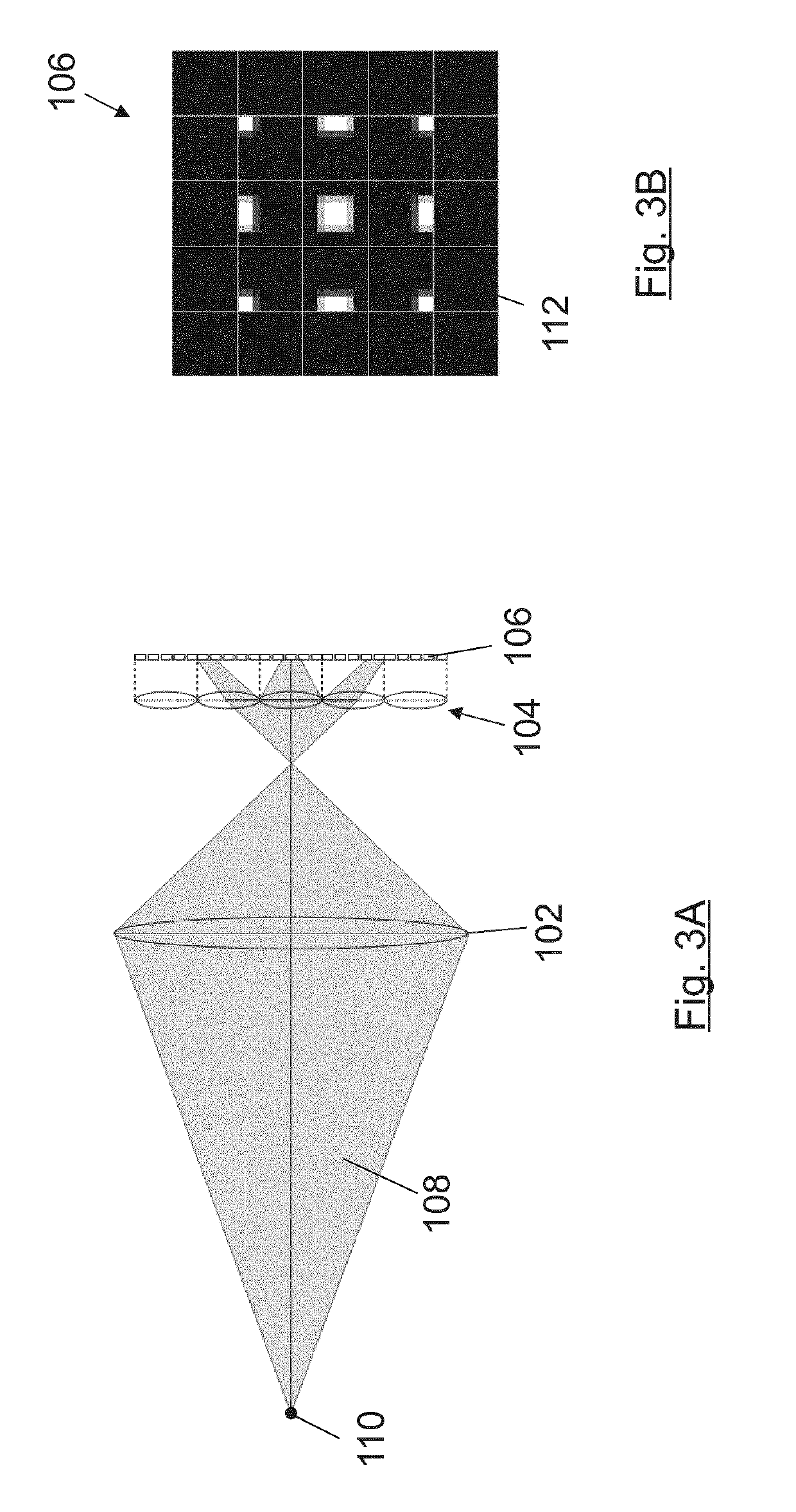
[0120]The present invention relates to a device and method for generating a depth map from a light field. A light field can be captured by multiple kinds of devices. For simplicity, first only plenoptic cameras will be considered. Afterwards, the method is described when applying it to a multiview system consisting of one or more plenoptic cameras and one or more conventional cameras. Nevertheless, the method herein described can be applied to light fields captured by any other device, including other integral imaging devices.

[0121]A conventional camera only captures two-dimensional spatial information of the light rays captured by the sensor. In addition, colour information can be also captured by using the so-called Bayer patterned sensors or other colour sensors. A plenoptic camera captures not only this information but also the direction of arrival of the rays. Usually a plenoptic camera is made by placing a microlens array between the main lens and the sensor. Each of the micro...


PUM


Abstract

A device and method for obtaining depth information from a light field is provided. The method generating a plurality of epipolar images from a light field captured by a light field acquisition device; an edge detection step for detecting, in the epipolar images, edges of objects in the scene captured by the light field acquisition device; for each epipolar image, detecting valid epipolar lines formed by a set of edges; and determining the slopes of the valid epipolar lines. In a preferred embodiment, the method extend the epipolar images with additional information of images captured by additional image acquisition devices and obtain extended epipolar lines. The edge detection step calculates a second spatial derivative for each pixel of the epipolar images and detects the zero-crossings of the second spatial derivatives.

Description

TECHNICAL FIELD[0001]The present invention is comprised in the field of digital image processing, and more particularly to methods and systems for estimating distances and generating depth maps from images.BACKGROUND ART[0002]In the light field technology, multiview vision systems, such as a plenoptic camera or a multi-camera system (i.e. an array of several cameras), are frequently used to estimate depths of scenes. Plenoptic cameras are imaging devices capturing not only spatial information but also angular information of a scene, known as light field. The light field can be represented as a four-dimensional function LF(px,py,lx,ly), where px and py select the direction of arrival of the rays to the sensor and lx,ly are the spatial position of that ray.[0003]A plenoptic camera is typically formed by a microlens array placed in front of the image sensor. This image capture system is equivalent to capturing the scene from several points of view (the so-called plenoptic views, like s...

Claims


Application Information

Patent Timeline
IPC IPC(8): G06T7/557G06T7/13G06T5/00G06T7/593
CPCG06T7/557G06T7/13G06T5/002G06T7/593G06T2207/10052G06T2207/10012G06T2200/28G06T2207/10016G06T7/155
Inventor BLASCO CLARET, JORGE VICENTEMONTOLIU ALVARO, CARLESCALATAYUD CALATAYUD, ARNAUCARRION, LETICIAMARTINEZ USO, ADOLFO
Owner PHOTONIC SENSORS & ALGORITHMS SL
Why Eureka
Try Eureka