Eclipse cursor for mixed reality displays

a mixed reality display and cursor technology, applied in the field of virtual, augmented, or mixed reality imaging and visualization systems, can solve the problems of difficult production of vr, ar, or mr technology that facilitates, and the human visual perception system is very complex, so as to achieve more emphasis on visual hierarchy and more natural and immersive user experien

Active Publication Date: 2019-08-01
MAGIC LEAP INC
View PDF28 Cites 75 Cited by
  • Summary
  • Abstract
  • Description
  • Claims
  • Application Information

AI Technical Summary

Benefits of technology

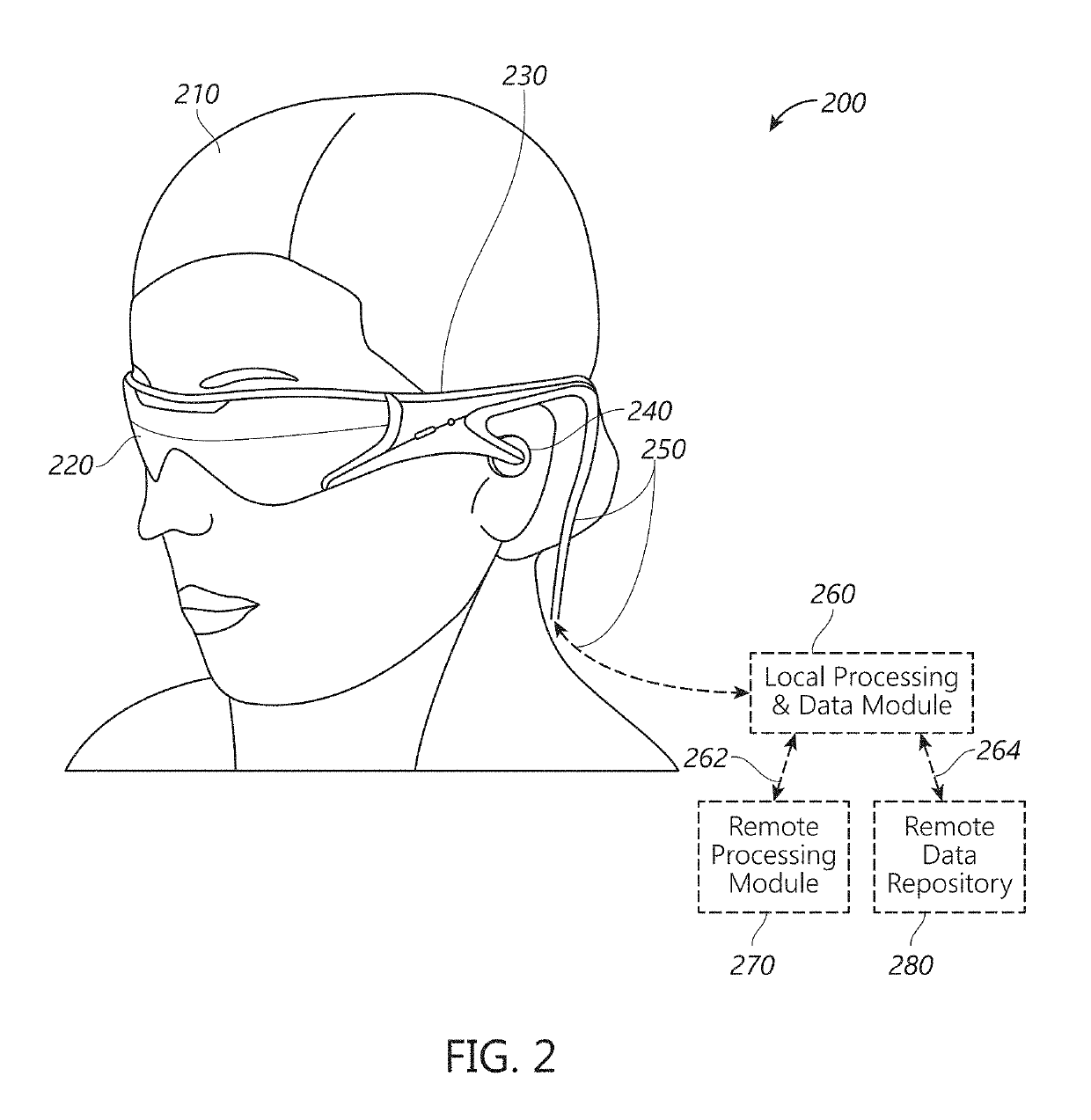
[0004]Techniques for displaying a cursor and a focus indicator associated with real or virtual objects in a virtual, augmented, or mixed reality environment by a wearable display device are described. For example, rendering the cursor in front of objects in the environment tends to occlude the object and place more emphasis in the visual hierarchy on the cursor itself rather than a target object being interacted with. Accordingly, embodiments of the wearable system can utilize an eclipse cursor that moves behind the target object (e.g., so that the cursor is “eclipsed” by the target object), which tends to preserve the emphasis on the target object, rather than the cursor, in the user's visual hierarchy. To aid the user in navigating the cursor among the objects in the environment, the system can render a focus indicator around objects near the cursor. The focus indicator may comprise a halo, shading, or highlighting around at least portions of objects near the cursor. The focus indicator may be emphasized (e.g., brighter, a different color or shade, or larger size) closer to the cursor (and deemphasized farther from the cursor), which provides visual cues to the user in navigating the cursor among objects in the environment and selecting a target object. The eclipse cursor and focus indicator can provide the user with a more natural and immersive user experience.
[0005]In various embodiments, a wearable display system can determine a spatial relationship between a user-movable cursor and one or more target objects within the environment. For example, the user may move the cursor by actuating a hand-held user input device (e.g., a totem). The wearable system may render a focus indicator (e.g., a halo, shading, or highlighting) around or adjacent to objects that are near the cursor. The focus indicator may be emphasized in directions closer to the cursor and deemphasized in directions farther from the cursor. When the cursor overlaps with a target object, the system can render the cursor behind the object (or not render the cursor at all), so the object is not occluded by the cursor (e.g., the object eclipses the cursor). The cursor and focus indicator can provide the user with positional feedback and help the user navigate among objects in the environment.

Problems solved by technology

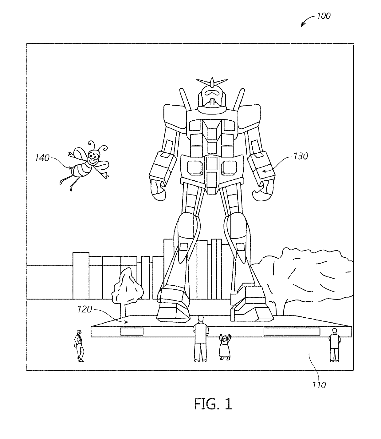
As it turns out, the human visual perception system is very complex, and producing a VR, AR, or MR technology that facilitates a comfortable, natural-feeling, rich presentation of virtual image elements amongst other virtual or real-world imagery elements is challenging.

Method used


Image

  • Eclipse cursor for mixed reality displays
  • Eclipse cursor for mixed reality displays
  • Eclipse cursor for mixed reality displays

Examples


example focus

Indicators

[0176]FIGS. 19-22 illustrate various examples of focus indicators that can be rendered by the system. The focus indicators 1302 can be circular (e.g., as shown in FIGS. 18, 19, and 21), rectangular (e.g., as shown in FIG. 20), or other shapes. In some cases, the focus indicator can include a label disposed adjacent (e.g., above, below, or to the side of) an object 1302. For example, FIG. 19 shows a label “Search” to the side of the object 1302 and FIG. 20 shows a label “Gather pages” above the object 1302. The label can be emphasized (e.g., made brighter) when the object is selected to provide a visual cue regarding the object to the user. Although these examples show textual labels, the label can be any graphical element. FIG. 22 shows an example where an application selection icon has been selected by the user, which permits the user to select among applications such as a browser, a social network, etc. In FIG. 22, the user has selected the Browser application and the sy...

example software

Code

[0183]Appendix A includes an example of code in the C# programming language that can be used to perform an embodiment of the eclipse cursor technology described herein. An embodiment of the process 2300 can be implemented at least in part by the example code in Appendix A. Appendix A also includes description of the software code. The disclosure of Appendix A is intended to illustrate an example implementation of various features of the eclipse cursor technology and is not intended to limit the scope of the technology. Appendix A is hereby incorporated by reference herein in its entirety so as to form a part of this specification.

Examples of a Portion of a Display with an Icon or a Graphical User Interface

[0184]FIGS. 24-28 are front views of examples of a portion of a display screen with an icon. In these examples, the icon comprises a stylized representation of a head that is mostly within a circle. FIGS. 24-28 show examples a focus indicator at least partially surrounding the ...


PUM


Abstract

Systems and methods for displaying a cursor and a focus indicator associated with real or virtual objects in a virtual, augmented, or mixed reality environment by a wearable display device are disclosed. The system can determine a spatial relationship between a user-movable cursor and a target object within the environment. The system may render a focus indicator (e.g., a halo, shading, or highlighting) around or adjacent objects that are near the cursor. The focus indicator may be emphasized in directions closer to the cursor and deemphasized in directions farther from the cursor. When the cursor overlaps with a target object, the system can render the object in front of the cursor (or not render the cursor at all), so the object is not occluded by the cursor. The cursor and focus indicator can provide the user with positional feedback and help the user navigate among objects in the environment.

Description

COPYRIGHT STATEMENT[0001]A portion of the disclosure of this patent document contains material which is subject to copyright protection. The copyright owner has no objection to the facsimile reproduction by anyone of the patent document or the patent disclosure, as it appears in the Patent and Trademark Office patent file or records, but otherwise reserves all copyright rights whatsoever.FIELD[0002]The present disclosure relates to virtual, augmented, or mixed reality imaging and visualization systems and more particularly to assigning a focus indicator to one or more real or virtual objects in the field of view of a user.BACKGROUND[0003]Modern computing and display technologies have facilitated the development of systems for so called “virtual reality”, “augmented reality”, or “mixed reality” experiences, wherein digitally reproduced images or portions thereof are presented to a user in a manner wherein they seem to be, or may be perceived as, real. A virtual reality, or “VR”, scen...

Claims


Application Information

Patent Timeline
Patent Type & Authority Applications(United States)
IPC IPC(8): G09G5/08G06F3/0481G09G5/377G06F3/01
CPCG09G5/08G06F3/04812G09G5/377G06F3/011G09G2354/00G09G2340/12G06F3/147G09G2340/14G06F3/04842G02B27/017G02B2027/0187G02B2027/0138
Inventor DAY, JOHN AUSTINPAZMINO, LORENAPETTY, JAMES CAMERONHOOVER, PAUL ARMISTEADSORRELL, CHRISPOWDERLY, JAMES M.NILES, SAVANNAH
Owner MAGIC LEAP INC
Why Eureka
Try Eureka