
Eureka
For R&D, Eureka makes reading and utilizing patents & technical documents easy.
Eureka AIR
Designed for self-driven R&D workflows. Generate viable solutions, solve complex R&D challenges, empower your innovation with AI.

Eureka Materials
Designed for material experts only. Revolutionize your material R&D, from search, analyze, to developing new materials.

TechResearch
Generate reliable direction feasibility study reports for your R&D in just a few steps.

TechSeek
Discover and master advanced knowledge NOW. Basics, ideas, possibilities, all at once.

TechMind
As an expert in R&D Theories, TechMind can generates customized viable solutions instantly.

TechRisk
Analyze your overall solution with one click, know your potential R&D risks in advance.

TechMonitor
Get weekly tech updates, stay abreast of the latest tech innovations and key insights.
Imaging optical lens assembly, imaging apparatus and electronic device
- Summary
- Abstract
- Description
- Claims
- Application Information
AI Technical Summary
Benefits of technology
Problems solved by technology
Method used
Image

Examples
1st embodiment
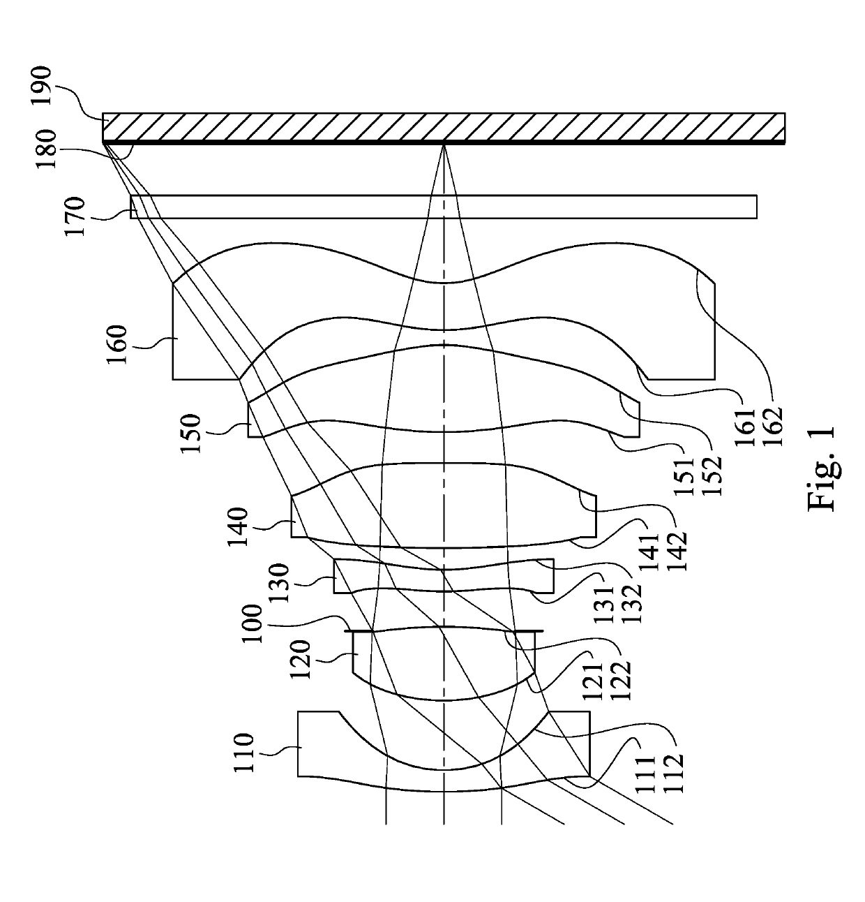
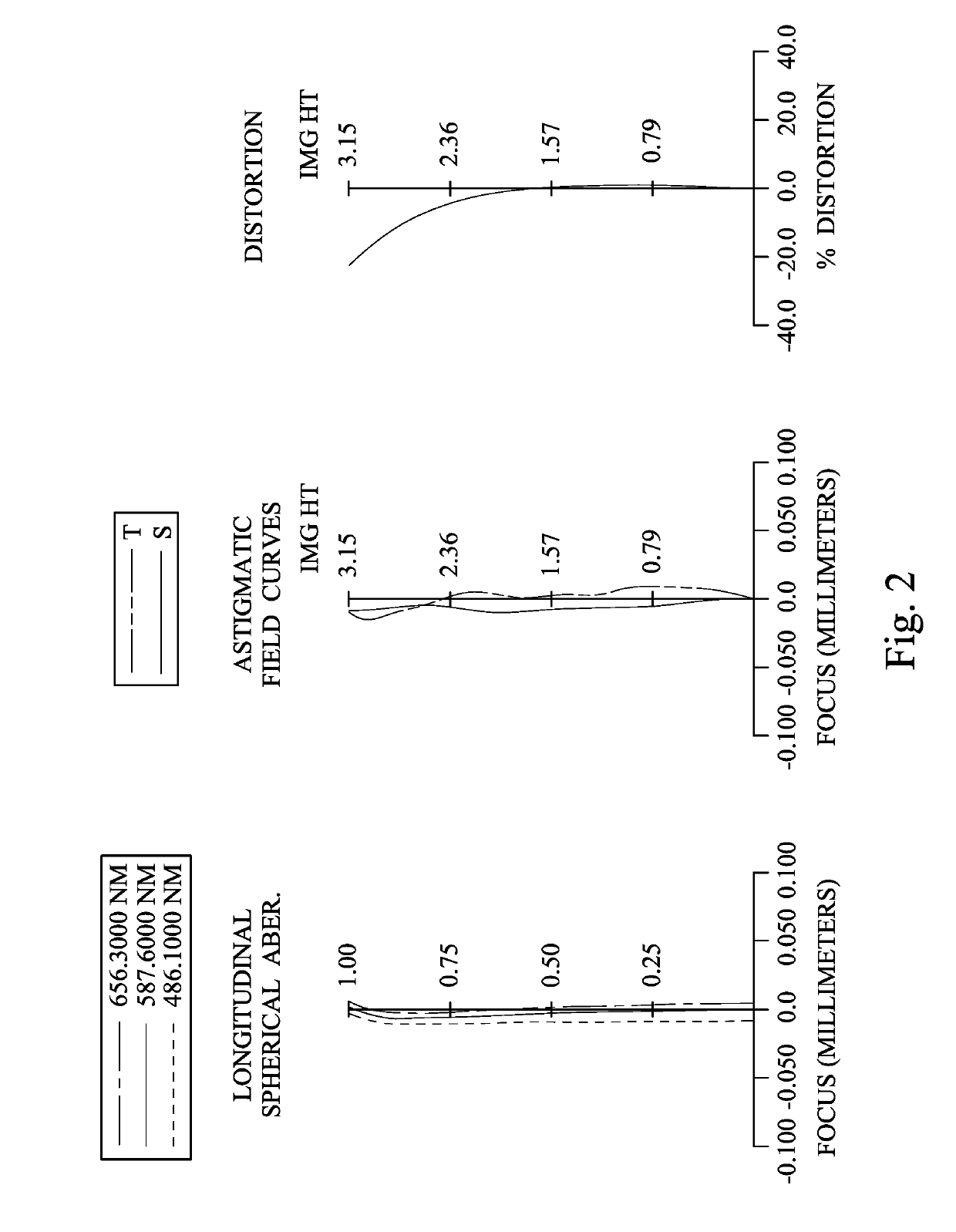
[0078]FIG. 1 is a schematic view of an imaging apparatus according to the 1st embodiment of the present disclosure. FIG. 2 shows spherical aberration curves, astigmatic field curves and a distortion curve of the imaging apparatus according to the 1st embodiment. In FIG. 1, the imaging apparatus includes an imaging optical lens assembly (its reference numeral is omitted) and an image sensor 190. The imaging optical lens assembly includes, in order from an object side to an image side, a first lens element 110, a second lens element 120, an aperture stop 100, a third lens element 130, a fourth lens element 140, a fifth lens element 150, a sixth lens element 160, an IR-cut filter 170 and an image surface 180. The image sensor 190 is disposed on the image surface 180 of the imaging optical lens assembly. The imaging optical lens assembly includes six lens elements (110, 120, 130, 140, 150 and 160) without additional one or more lens elements inserted between the first lens element 110 a...
2nd embodiment
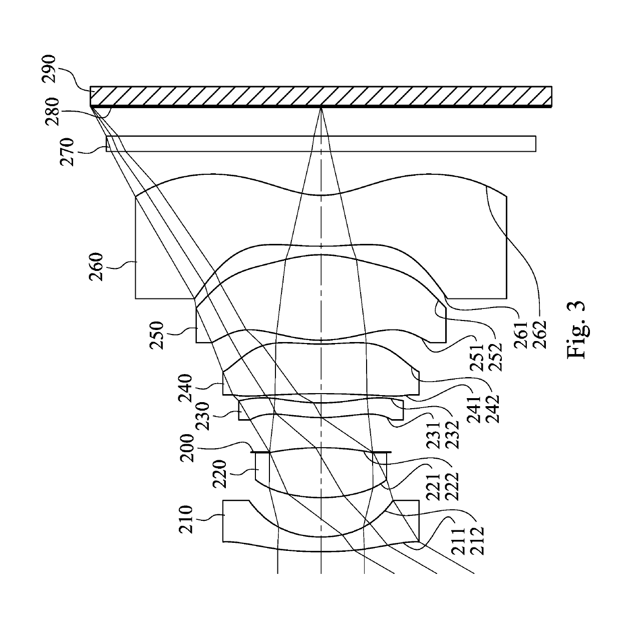
[0106]FIG. 3 is a schematic view of an imaging apparatus according to the 2nd embodiment of the present disclosure. FIG. 4 shows spherical aberration curves, astigmatic field curves and a distortion curve of the imaging apparatus according to the 2nd embodiment. In FIG. 3, the imaging apparatus includes an imaging optical lens assembly (its reference numeral is omitted) and an image sensor 290. The imaging optical lens assembly includes, in order from an object side to an image side, a first lens element 210, a second lens element 220, an aperture stop 200, a third lens element 230, a fourth lens element 240, a fifth lens element 250, a sixth lens element 260, an IR-cut filter 270 and an image surface 280. The image sensor 290 is disposed on the image surface 280 of the imaging optical lens assembly. The imaging optical lens assembly includes six lens elements (210, 220, 230, 240, 250 and 260) without additional one or more lens elements inserted between the first lens element 210 a...
3rd embodiment
[0117]FIG. 5 is a schematic view of an imaging apparatus according to the 3rd embodiment of the present disclosure. FIG. 6 shows spherical aberration curves, astigmatic field curves and a distortion curve of the imaging apparatus according to the 3rd embodiment. In FIG. 5, the imaging apparatus includes an imaging optical lens assembly (its reference numeral is omitted) and an image sensor 390. The imaging optical lens assembly includes, in order from an object side to an image side, a first lens element 310, a second lens element 320, an aperture stop 300, a third lens element 330, a fourth lens element 340, a fifth lens element 350, a sixth lens element 360, an IR-cut filter 370 and an image surface 380. The image sensor 390 is disposed on the image surface 380 of the imaging optical lens assembly. The imaging optical lens assembly includes six lens elements (310, 320, 330, 340, 350 and 360) without additional one or more lens elements inserted between the first lens element 310 a...
PUM
 Abstract
Description
Claims
Application Information
 - R&D Engineer
- R&D Manager
- IP Professional
- Industry Leading Data Capabilities
- Powerful AI technology
- Patent DNA Extraction
Browse by: Latest US Patents, China's latest patents, Technical Efficacy Thesaurus, Application Domain, Technology Topic, Popular Technical Reports.
© 2024 PatSnap. All rights reserved.Legal|Privacy policy|Modern Slavery Act Transparency Statement|Sitemap|About US| Contact US: help@patsnap.com