Method, device and storage medium for determining camera posture information

a technology of information and camera posture, applied in the field of computer technologies, can solve the problems of affecting the running efficiency and relatively low precision of information, and achieve the effects of low precision, fast optical flow speed and slow speed

Active Publication Date: 2019-08-08
TENCENT TECH (SHENZHEN) CO LTD
View PDF0 Cites 8 Cited by
  • Summary
  • Abstract
  • Description
  • Claims
  • Application Information

AI Technical Summary

Benefits of technology

[0015]Because a first homography is obtained in a feature point detection manner according to a template image and a second image, an output result has a slow speed and low precision, and because a second homography is obtained through estimation according to an optical flow tracking result of a first image and the second image and an optical flow tracking result of the template image and the first image, the o

Problems solved by technology

When the affine transformation is obvious, if feature points of one image layer in the Marker image is matched with feature points in the current image, the obtained camera pose information has relatively low precision; and if a plura

Method used


Image

  • Method, device and storage medium for determining camera posture information
  • Method, device and storage medium for determining camera posture information
  • Method, device and storage medium for determining camera posture information

Examples


first embodiment

[0127]Optionally, on the basis of the first embodiment corresponding to FIG. 7, in a second optional embodiment of the method for determining camera pose information according to the embodiments of this application, the template image corresponds to a plurality of grids arranged in arrays; and

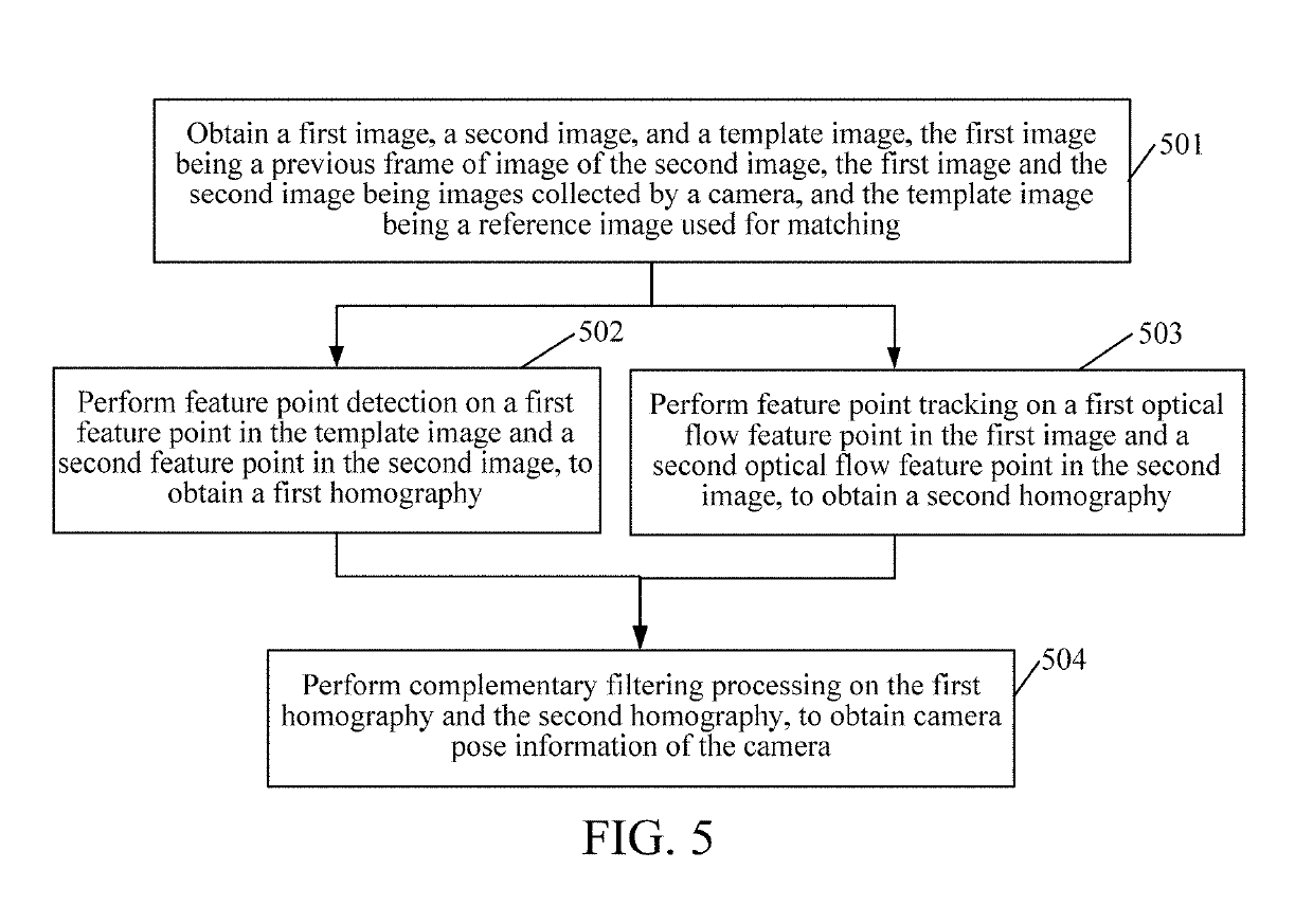
[0128]the performing feature point detection on a first feature point in the template image and a second feature point in the second image, to obtain a first homography includes:

[0129]matching the first feature point in the template image with the second feature point in the second image, and determining a set of feature point pairs in each target grid of the plurality of grids, the feature point pair including: a first feature point located in the target grid, and a feature point that is in the second feature point and that has the largest matching degree with the first feature point; and

[0130]calculating the first homography between the template image and the second image according to the fea...

third embodiment

[0145]Optionally, on the basis of the third embodiment corresponding to FIG. 7, in a fourth optional embodiment of the method for determining camera pose information according to the embodiments of this application, the determining the second homography according to the first target homography and the second target homography may include:

[0146]obtaining the second target homography from the template image to the first image; and

[0147]calculating the second homography from the second image to the template image according to the first target homography and the second target homography.

[0148]In this embodiment, in the process for the apparatus for determining camera pose information to determine the second homography or before the apparatus determines the second homography, a third optical flow feature point needs to be obtained in the template image, then, a matching point of the template image and the first image is found according to the third optical flow feature point and the firs...

seventh embodiment

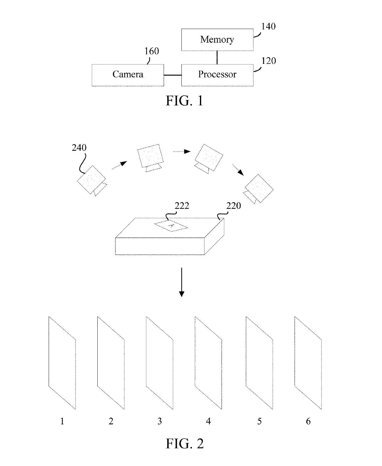
[0160]The process for transforming a homography into a rotation and translation matrix may be understood as a process for transforming two-dimensional coordinates to three-dimensional coordinates. For the specific implementation, reference may be made to a seventh embodiment corresponding to FIG. 7. After the three-dimensional coordinates are obtained, the position of the camera in the real world when the camera collects the template image may be determined.

[0161]It may be understood that, for the apparatus for determining camera pose information, the time-consuming part is mainly on the detection. For a frame of image, it costs less than 10 ms at most for a tracker to track the frame of image, and it costs nearly 30 ms for a detector to detect the frame of image. Therefore, another alternative solution is fusing the first rotation and translation matrix and the second rotation and translation matrix instead of detection on each frame. Instead, detection and fusion of each frame are...


PUM


Abstract

Embodiments of this application disclose a method for determining camera pose information of a camera of a mobile terminal. The method includes: obtaining a first image, a second image, and a template image; performing feature point detection on a first feature point of the template image and a second feature point of the second image, to obtain a first homography; determining a first target homography according to a first optical flow feature point in the first image and a second optical flow feature point in the second image, and determining a second homography according to the first target homography and a second target homography; and performing complementary filtering processing on the first homography and the second homography, to obtain camera pose information of the camera. In the embodiments of this application, complementary filtering processing may be performed on two homographies obtained in a camera pose tracking process.

Description

CROSS-REFERENCE TO RELATED APPLICATIONS[0001]This application is a continuation application of PCT / CN2018 / 093418, entitled “METHOD, APPARATUS AND DEVICE FOR DETERMINING CAMERA POSTURE INFORMATION, AND STORAGE MEDIUM” filed on Jun. 28, 2018, which claims priority to Chinese Patent Application No. 201710552105.1, entitled “METHOD FOR DETERMINING CAMERA POSE INFORMATION AND RELATED APPARATUS” filed with China National Intellectual Property Administration on Jul. 7, 2017, both of which are incorporated by reference in their entirety.FIELD OF THE TECHNOLOGY[0002]This application relates to the field of computer technologies, and in particular, to a method, an apparatus, and a device for determining camera pose information, and a storage medium.BACKGROUND OF THE DISCLOSURE[0003]An augmented Reality (AR) technology is a technology for calculating positions and angles of camera images in real time and adding corresponding images, videos or 3D models. This technology is aimed to apply the vi...

Claims


Application Information

Patent Timeline
IPC IPC(8): G06K9/46G06T5/20G06K9/62G06K9/34G06T3/00G06V10/75
CPCG06K9/4609G06T5/20G06K9/6211G06K9/34G06T3/0006G06T7/74G06T2207/30244G06T2207/10016G06T7/73G06T7/246G06T3/0012G06T7/269G06T2207/30204G06T2207/20076G06T2207/30208G06T2207/20016G06T7/70G06T7/248G06V20/10G06V20/20G06V10/225G06V10/17G06V10/462G06V10/75G06F18/22G06V10/26G06V10/443G06V10/757G06T7/00G06V10/10G06V10/40
Inventor LIN, XIANGKAIBAO, LINCHAOLIU, WEI
Owner TENCENT TECH (SHENZHEN) CO LTD
Why Eureka
Try Eureka