Sweeping robot and corresponding cleaning device

Active Publication Date: 2019-08-15
HIZERO APPLIANCES CORP
View PDF0 Cites 5 Cited by
  • Summary
  • Abstract
  • Description
  • Claims
  • Application Information

AI Technical Summary

Benefits of technology

[0004]According to various embodiments of the present application, there is provided a cleaning device that has a strong cleaning ability and a flexible

Problems solved by technology

In the process of cleaning the floor, the roller is easily stained with dirt, which is not conducive t

Method used


Image

  • Sweeping robot and corresponding cleaning device
  • Sweeping robot and corresponding cleaning device
  • Sweeping robot and corresponding cleaning device

Examples


Example

Embodiment 1

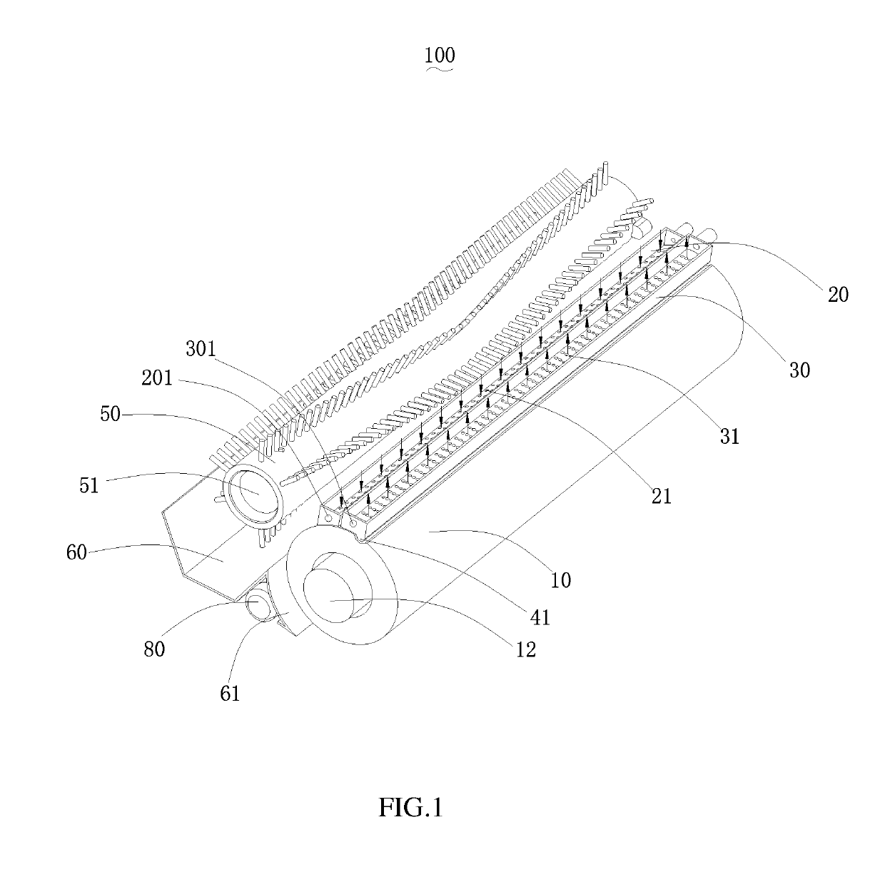
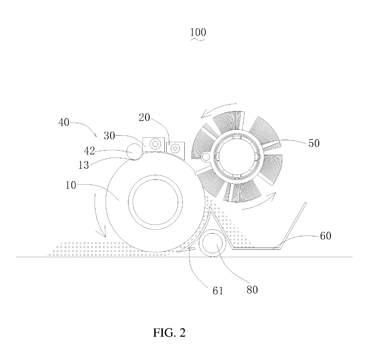
[0019]Referring to FIGS. 1 and 2, a cleaning robot according to a preferred embodiment of the present disclosure includes a shell and a cleaning device 100 located in the shell. The cleaning device 100 includes a flexible roller 10 and a roller motor 12 for driving the flexible roller 10 to rotate. The cleaning device 100 also includes a clean water sink 20 spaced apart from the flexible roller 10 by a gap, a sewage sink 30 spaced apart from the flexible roller 10 by a gap, and a pressing member 40 for deforming the flexible roller 10 to press out the sewage. The cleaning device 100 also includes a roller brush 50 on a side of the flexible roller 10, a garbage collection box 60, and a water tank 70 for containing water. Wherein the bristles on the roller brush 50 contact the flexible roller 10, and the garbage collection box 60 is located at least partially below the roller brush 50. Solid waste is swept into the garbage collection box 60 and liquid waste is absorbed in ...

Example

Embodiment 2

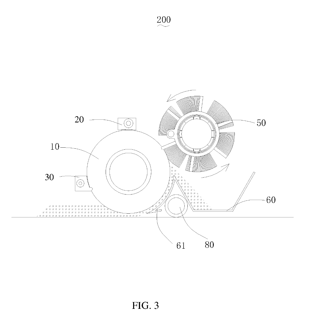
[0032]Referring to FIG. 3, the cleaning device 200 of the present embodiment is different from the first embodiment is that the clean water sink 20 is disposed above the flexible roller 10; the sewage sink 30 is disposed on one side of the flexible roller 10, and the top of the sewage sink 30 is closed. The sewage hole 31 is provided at the bottom of the sewage sink. 30, so that the sewage sink 30 is closer to the area where the sewage gathers, and the sewage is more easily discharged into the sewage sink 30. At this time, the pressing member 40 is a protrusion 41 provided at the bottom of the sewage sink 30. The protrusion 41 is press-fitted on the surface of the flexible roller 10. When the flexible roller 10 rotates, the protrusion 41 presses the sewage inside the flexible roller 10 to the sewage sink 30.

Example

Embodiment 3

[0033]Referring to FIG. 4, the cleaning device 300 of the present embodiment is different from the first embodiment in that the sewage sink 30 is disposed above the flexible roller 10, and a sewage hole 31 is provided at the bottom of the sewage sink 30. The clean water sink 20 is disposed above the sewage sink 30 and connected to the sewage sink 30. A clean water hole 21 is disposed at the bottom of the clean water sink 20. The clean water hole 21 communicates with the sewage sink 30. The clean water is first injected into the clean water sink 20, then flows from the clean water sink 20 onto the flexible roller 10 and into the sewage sink 30. At this time, it can also separate clean water and sewage, but the effect is not as good as in the first embodiment.

[0034]Further, one or both ends of the clean water sink 20 communicate with the clean water tank 73 through the clean water pipe 75, and one or both ends of the sewage sink 30 communicate with the sewage tank 74 throu...


PUM


Abstract

The disclosure relates to a sweeping robot and a cleaning device. The sweeping robot includes: a flexible roller for cleaning the ground, a roller motor for driving the flexible roller to rotate, a pressing member for deforming the flexible roller to press out sewage. Clean water in the clean water sink flows through the clean water hole to the flexible roller. The sweeping robot further includes a sewage sink. The sewage sink is provided with a sewage hole is adjacent to the pressing member. The pressing member deforms the flexible roller, causing sewage to be pressed out of the flexible member and flow through the sewage hole into the sewage sink. The sewage sink is separated from the clean water sink. The cleaning device of the present invention has strong cleaning ability, and the flexible roller is easy to clean.

Description

RELATED APPLICATIONS[0001]This application is a continuation-in-part of and claims priority to PCT / CN2018 / 076684, filed on Feb. 13, 2018, which is incorporated herein by reference.FIELD OF THE DISCLOSURE[0002]The present disclosure relates to the technical field of cleaning equipment, in particular to a cleaning robot and a cleaning device thereof.BACKGROUND OF THE DISCLOSURE[0003]Sweeping robots are self-cleaning devices that reduce the pressure on people to clean. Sweeping robots generally use the structure of roller brushes, rollers, sewage collecting tanks, and water tanks. Clean water from one end of a sewage collecting tank is supplied to the roller, and the sewage discharged from the roller is absorbed into the sewage collecting tank through negative pressure. This kind of structure mixes clean water and sewage in the process of cleaning and does not separate dirty sewage from clean water. In the process of cleaning the floor, the roller is easily stained with dirt, which is ...

Claims


Application Information

Patent Timeline
IPC IPC(8): A47L11/292A47L11/40
CPCA47L11/292A47L11/4016A47L11/4041A47L11/4011A47L11/4069A47L11/4083A47L11/4088A47L11/24A47L11/4013A47L11/4072A47L11/408A47L2201/00A47L7/0004
Inventor LI, YANG
Owner HIZERO APPLIANCES CORP
Why Eureka
Try Eureka