Joint component manufacturing method
a manufacturing method and joint technology, applied in the direction of rod connections, forging/pressing/hammering apparatuses, couplings, etc., can solve the problems of further reducing bonding force and weakening bonding force between the first and the second members, so as to facilitate the fitting of the hole and reduce the occurrence of buns.
- Summary
- Abstract
- Description
- Claims
- Application Information
AI Technical Summary
Benefits of technology
Problems solved by technology
Method used
Image
Examples
first embodiment
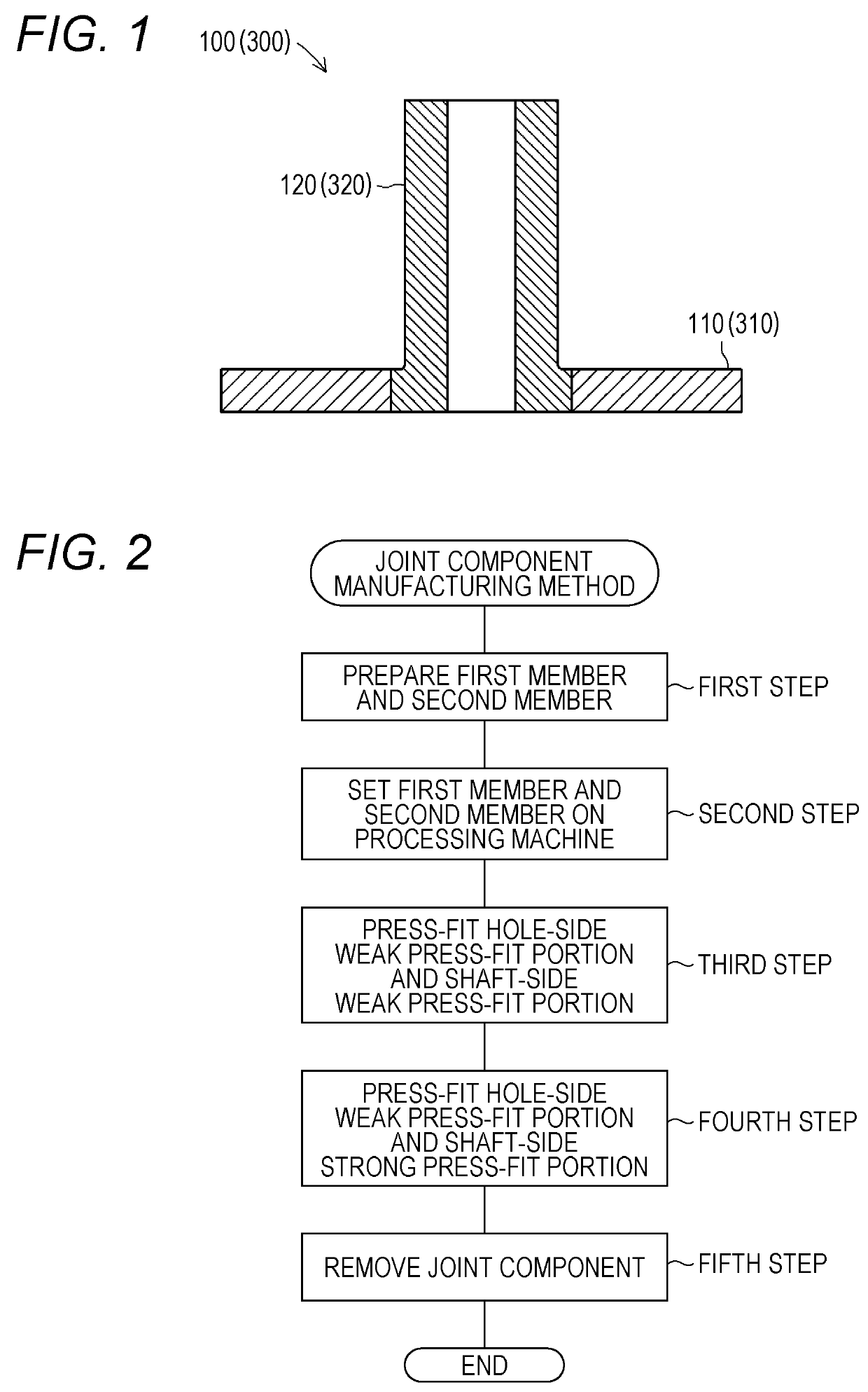
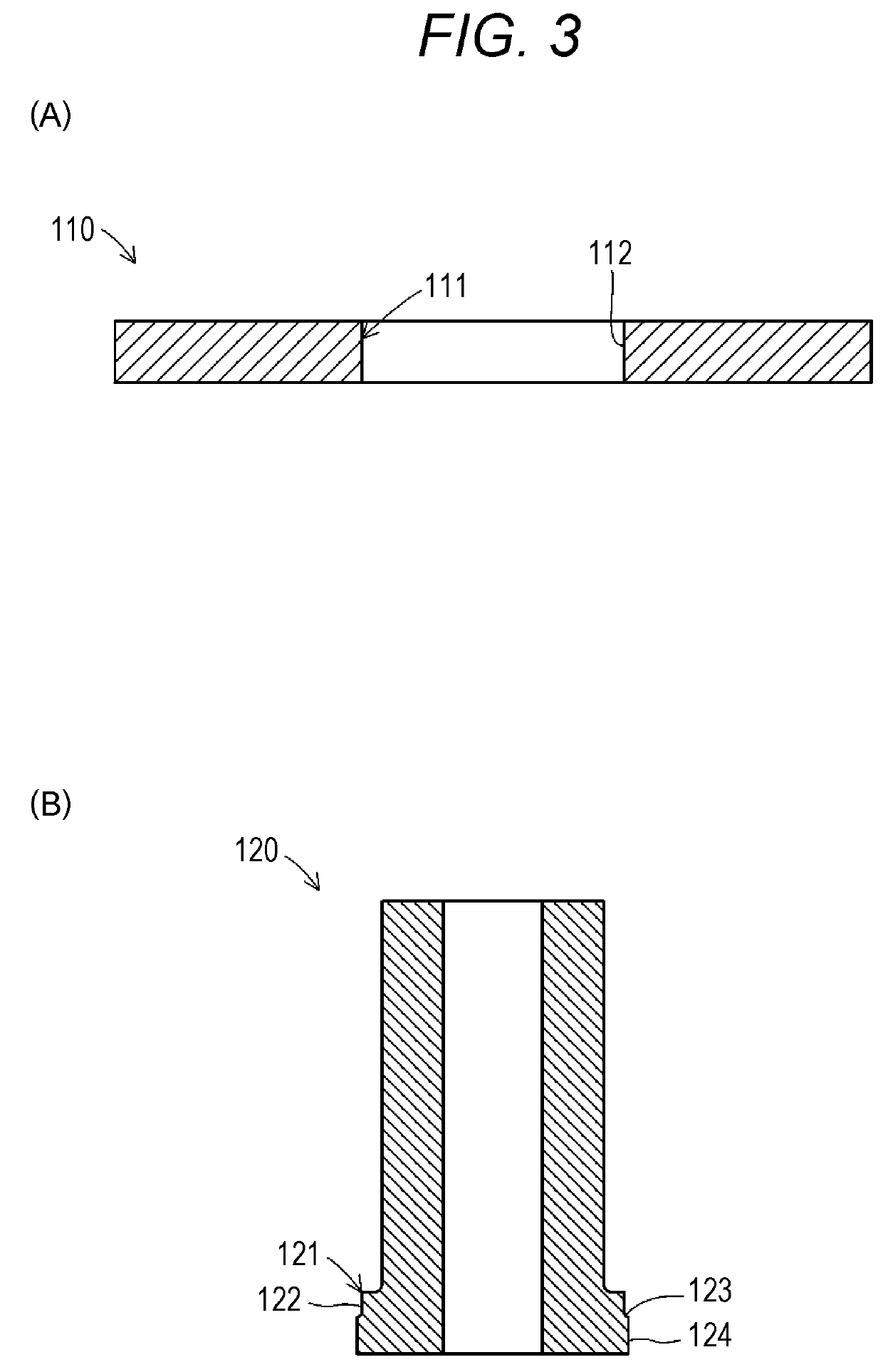
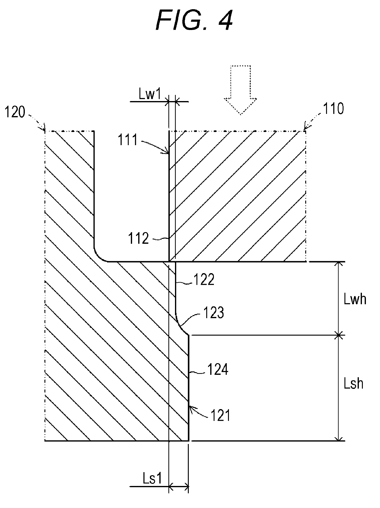
[0030]Hereinafter, a first embodiment of a joint component manufacturing method according to the present invention will be described with reference to the drawings. FIG. 1 is a schematic sectional view of an outline configuration of a joint component 100 formed by the joint component manufacturing method according to the present invention. Moreover, FIG. 2 is a flowchart of the flow of main steps in the method for manufacturing the joint component 100 according to the first embodiment of the present invention. Note that for the sake of easy understanding of the present invention, each figure referred in the present specification is schematically illustrated, and for example, some components are exaggeratingly illustrated. Thus, the dimensions and ratio of each component may be changed.
[0031]First, the joint component 100 formed by the joint component manufacturing method according to the present invention will be briefly described. The joint component 100 mainly includes a first mem...
second embodiment
[0060]Next, a second embodiment of a joint component manufacturing method according to the present invention will be described with reference to FIGS. 8 to 11. In the second embodiment, differences from the first embodiment will be mainly described.
[0061]A joint component 300 configured in a manner similar to that of the joint component 100 mainly includes a first member 310 and a second member 320. In the first member 310, each of a hole-side weak press-fit portion 312, a gradually-changing portion 313, and a hole-side strong press-fit portion 314 is formed at a through-hole-shaped hole 311. Moreover, the second member 320 is configured such that each of a shaft-side weak press-fit portion 322, a gradually-changing portion 323, and a shaft-side strong press-fit portion 324 is formed at a cylindrical shaft portion 321.
[0062]As illustrated in FIG. 9, the hole-side weak press-fit portion 312 and the shaft-side weak press-fit portion 322 are portions formed with a second weak press-fit...
PUM
| Property | Measurement | Unit |
|---|---|---|
| diameter | aaaaa | aaaaa |
| diameter | aaaaa | aaaaa |
| diameter | aaaaa | aaaaa |
Abstract
Description
Claims
Application Information
 - R&D
- Intellectual Property
- Life Sciences
- Materials
- Tech Scout
- Unparalleled Data Quality
- Higher Quality Content
- 60% Fewer Hallucinations
Browse by: Latest US Patents, China's latest patents, Technical Efficacy Thesaurus, Application Domain, Technology Topic, Popular Technical Reports.
© 2025 PatSnap. All rights reserved.Legal|Privacy policy|Modern Slavery Act Transparency Statement|Sitemap|About US| Contact US: help@patsnap.com


