Vehicle Brake System With Secondary Brake Module

Active Publication Date: 2019-08-15
KELSEY HAYES CO
View PDF5 Cites 16 Cited by
  • Summary
  • Abstract
  • Description
  • Claims
  • Application Information

AI Technical Summary

Problems solved by technology

Under these conditions, a driver can easily apply excessive braking pressure thus causing one or more wheels to lock, resulting in excessive slippage between the wheel and road surface.
Such wheel lock-up conditions can lead to greater stopping distances and possible loss of directional control.
Excessive wheel speed during vehicle acceleratio

Method used


Image

  • Vehicle Brake System With Secondary Brake Module
  • Vehicle Brake System With Secondary Brake Module
  • Vehicle Brake System With Secondary Brake Module

Examples


Embodiment Construction

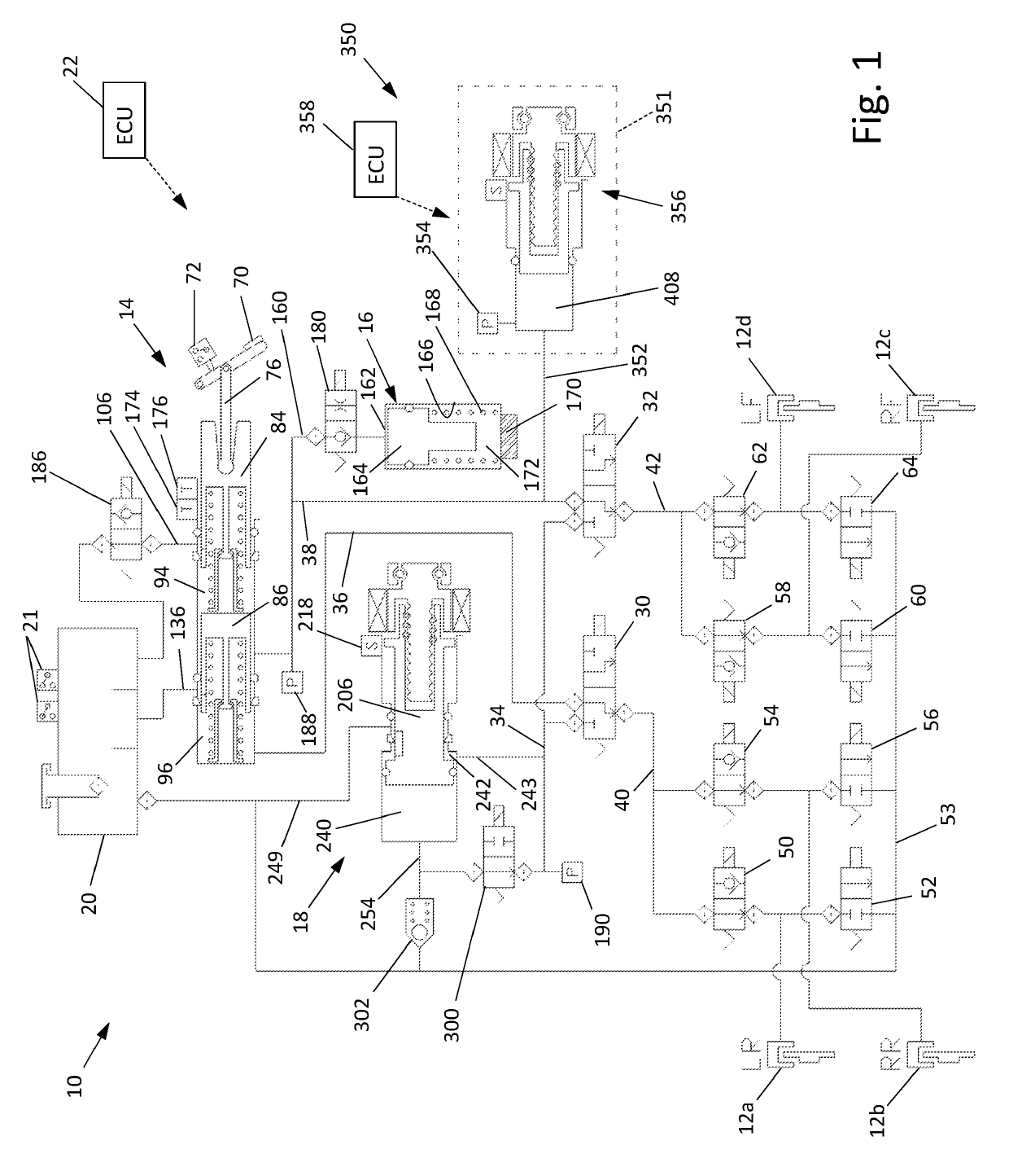
[0018]Referring now to the drawings, there is schematically illustrated in FIG. 1 a vehicle brake system, indicated generally at 10. The brake system 10 is a hydraulic braking system in which fluid pressure from a source is operated to apply braking forces for the brake system 10. The brake system 10 may suitably be used on a ground vehicle such as an automotive vehicle having four wheels. Furthermore, the brake system 10 can be provided with other braking functions such as anti-lock braking (ABS) and other slip control features to effectively brake the vehicle, as will be discussed below. In the illustrated embodiment of the brake system 10, there are four wheel brakes 12a, 12b, 12c, and 12d. The wheel brakes 12a, 12b, 12c, and 12d can have any suitable wheel brake structure operated by the application of pressurized brake fluid. The wheel brakes 12a, 12b, 12c, and 12d may include, for example, a brake caliper mounted on the vehicle to engage a frictional element (such as a brake d...


PUM


Abstract

A brake system has a wheel brake and is operable under a non-failure normal braking mode and a manual push-through mode. The system includes a master cylinder operable by a brake pedal during a manual push-through mode to provide fluid flow at an output for actuating the wheel brake. A first source of pressurized fluid provides fluid pressure for actuating the wheel brake under a normal braking mode. A secondary brake module includes a plunger assembly for generating brake actuating pressure for actuating the wheel brake under the manual push-through mode.

Description

CROSS-REFERENCE TO RELATED APPLICATIONS[0001]This application claims the benefit of U.S. Provisional Application No. 62 / 630,519, filed Feb. 14, 2018, the disclosure of which is incorporated herein by reference.BACKGROUND OF THE INVENTION[0002]This invention relates in general to vehicle braking systems. Vehicles are commonly slowed and stopped with hydraulic brake systems. These systems vary in complexity but a base brake system typically includes a brake pedal, a tandem master cylinder, fluid conduits arranged in two similar but separate brake circuits, and wheel brakes in each circuit. The driver of the vehicle operates a brake pedal which is connected to the master cylinder. When the brake pedal is depressed, the master cylinder generates hydraulic forces in both brake circuits by pressurizing brake fluid. The pressurized fluid travels through the fluid conduit in both circuits to actuate brake cylinders at the wheels to slow the vehicle.[0003]Base brake systems typically use a b...

Claims


Application Information

Patent Timeline
IPC IPC(8): B60T13/62B60T13/74B60T11/16B60T8/17B60T17/06B60T8/40B60T13/66
CPCB60T13/62B60T13/745B60T11/165B60T8/17B60T17/06B60T8/4081B60T13/662B60T2270/10B60T2270/20B60T2270/30B60T13/686B60T7/042B60T13/146B60T2270/402B60T8/4018
Inventor GANZEL, BLAISELITTLEJOHN, DERON CRAIG
Owner KELSEY HAYES CO
Why Eureka
Try Eureka