
Main bearing for crankshaft of internal combustion engine

a crankshaft and internal combustion engine technology, applied in the direction of crankshafts, sliding contact bearings, machines/engines, etc., can solve the problems of large frictional loss, frictional loss, and frictional loss, and achieve the effect of increasing output, facilitating frictional loss, and improving fuel efficiency

Inactive Publication Date: 2019-08-15
DAIDO METAL CO LTD
View PDF15 Cites 1 Cited by
  • Summary
  • Abstract
  • Description
  • Claims
  • Application Information

AI Technical Summary

Benefits of technology

The present invention aims to improve lubrication performance in internal combustion engines. It aims to prevent foreign objects, such as metal scraps and casting sand, from entering the lubricating oil path and causing frictional loss. This is achieved by designing a main bearing that increases lubricating oil supply to the slide surface during operation and prevents foreign objects from entering the slide surface.

Problems solved by technology

Accordingly, the crankshaft is in contact with the slide surface in the vicinity of an axial end of the main bearing, and therefore readily causes a frictional loss.
A conventional half bearing in which a plurality of small recesses are formed on a slide surface as lubricating oil pockets as described in JP-A-2000-504089 has the problem that, because a lubricating oil groove of a main bearing is not in communication with the small recesses, supply of oil to the vicinity of an axial end of the slide surface is not sufficient, and the slide surface in the vicinity of the axial end is in contact with the surface of a crankshaft after all, so that a frictional loss becomes large.
Accordingly, there is the problem that the foreign matters contained in the lubricating oil groove enter the tilted grooves together with lubricating oil, further enter a space between a slide surface of the main bearing and the surface of the crankshaft, and then contact the slide surface and the surface of the crankshaft, so that a frictional loss is caused.

Method used


Image

  • Main bearing for crankshaft of internal combustion engine
  • Main bearing for crankshaft of internal combustion engine
  • Main bearing for crankshaft of internal combustion engine

Examples


embodiment 1

(Overall Configuration of Bearing Device)

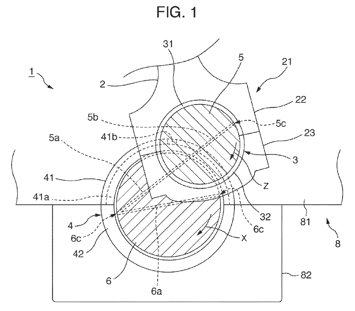
[0030]As shown in FIG. 1, a bearing device 1 according to the present embodiment includes a journal portion 6 supported by a bottom part of a cylinder block 8, a crankpin 5 which is formed integrally with the journal portion 6 to rotate around the journal portion 6, and a connecting rod 2 which transmits reciprocating movement to the crankpin 5 from an internal combustion engine. The bearing device 1 further includes a main bearing 4 which rotatably bears the journal portion 6, and a connecting rod bearing 3 which rotatably bears the crankpin 5, as slide bearings for bearing a crankshaft.

[0031]It should be noted that the crankshaft includes a plurality of journal portions 6 and a plurality of crankpins 5, however, one journal portion 6 and one crankpin 5 are shown in the drawings for convenience of explanation, and described accordingly. In FIG. 1, regarding a positional relationship in the depth direction of the drawing sheet, the journal po...

embodiment 2

[0049]As shown in FIG. 8 and FIG. 9, in contrast to the upper half bearing 41 according to Embodiment 1, an axial groove 71a according to Embodiment 2 is formed so as not to open at the axial end of the upper half bearing 41. That is, the axial length L2 of the axial groove 71a is smaller than the axial length L1 of the upper half bearing 41. The upper half bearing 41 according to Embodiment 2 has the same configuration as that according to Embodiment 1 in other respects.

(Action and Effects)

[0050]The present embodiment has advantageous effects similar to those in Embodiment 1. Further, since the axial groove 71a is not open at both axial ends of the upper half bearing 41, the oil in the axial groove 71a less easily flows out of the bearing than in Embodiment 1.

embodiment 3

[0051]As shown in FIG. 10 and FIG. 11, in contrast to the upper half bearing according to Embodiment 1, the upper half bearing 41 according to Embodiment 3 has axial grooves 71a formed at even intervals in the circumferential direction over the entire inner peripheral surface of the upper half bearing 41. The axial length L2 of the axial groove 71a is smaller than the axial length L1 of the upper half bearing 41 as in Embodiment 2, and therefore, the axial groove 71a is configured so as not to open at both axial ends of the upper half bearing 41. The upper half bearing 41 according to Embodiment 3 has the same configuration as that according to Embodiment 1 in other respects.

[0052]When the present invention is applied to a main bearing for a crankshaft of an internal combustion engine of a general passenger vehicle, that is, a main bearing for a crankshaft in which a diameter of a journal portion 6 is approximately 40 mm to 100 mm, the plurality of axial grooves 71a provided at even...


PUM


Abstract

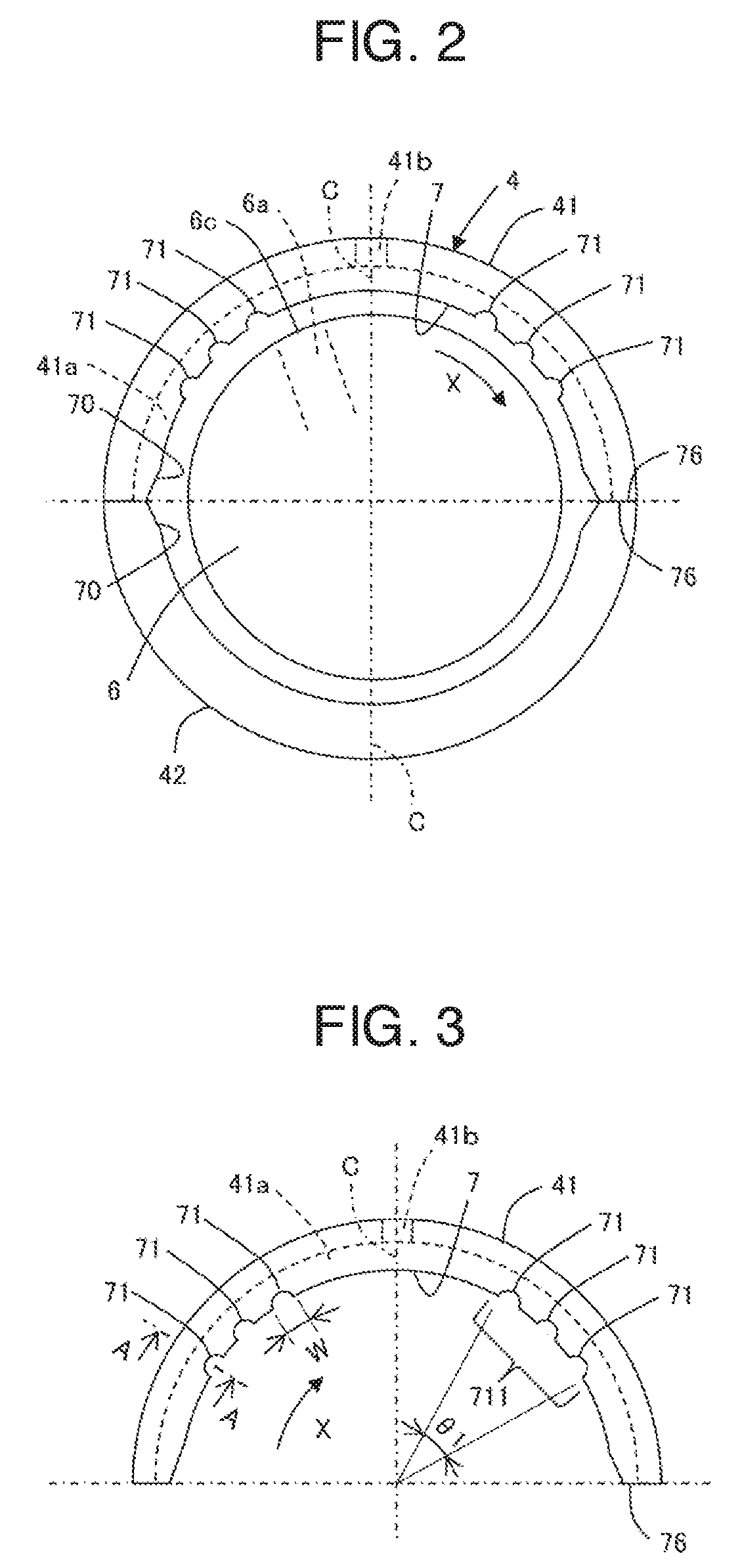
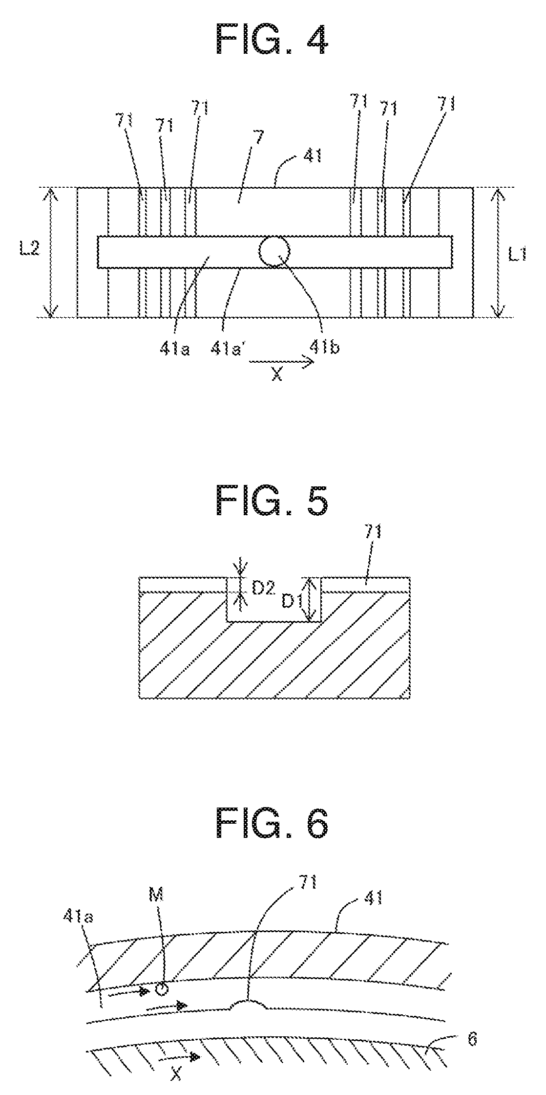
A main bearing for a journal portion of a crankshaft includes a pair of upper and lower half bearings combined with each other to form a cylindrical shape. Only the upper half bearing includes an oil groove formed on its inner peripheral surface to extend in a circumferential direction, an oil hole piercing from the oil groove to an outer peripheral surface of the upper half bearing, and a plurality of axial grooves formed on its inner peripheral surface to extend in an axial direction so as to intersect with the oil groove. A groove depth D2 of the axial groove is not more than 10% of a groove depth D1 of the oil groove, and an axial length L2 of the axial groove is not less than 70% of an axial length L1 of the upper half bearing.

Description

BACKGROUND OF THE INVENTION(1) Field of the Invention[0001]The present invention relates to a main bearing, and particularly to a main bearing for a crankshaft of an internal combustion engine that bears a journal portion of the crankshaft, and is configured so that lubricating oil supplied to an inner peripheral surface of the main bearing is supplied, through an internal lubricating oil path in the crankshaft, to an inner peripheral surface of a connecting rod bearing that bears a crankpin.(2) Description of Related Art[0002]A crankshaft of an internal combustion engine is, at a journal portion thereof, borne by a cylinder block bottom part of the internal combustion engine via a main bearing composed of a pair of half bearings. For the main bearing, lubricating oil discharged by an oil pump is fed into a lubricating oil groove formed along an inner peripheral surface of the main bearing, from an oil gallery formed in a cylinder block wall through a through-hole (oil hole) formed ...

Claims


Application Information

Patent Timeline
Patent Type & Authority Applications(United States)
IPC IPC(8): F16C9/02F16C33/10
CPCF16C9/02F16C33/1065F16N1/00F16C3/14F16C33/1045F16C33/1055F16C17/022F01M1/06F01M2001/062
Inventor AMANO, SEIJIWATANABE, TORU
Owner DAIDO METAL CO LTD
Learn More