Device and method for shielding at least one sub-wavelength-scale object from an incident electromagnetic wave

a technology of incident electromagnetic waves and shielding devices, applied in the field of shielding objects from electromagnetic waves, can solve the problems of not being suitable for static angular-selective shielding of some objects (e.g. qds) from incident electromagnetic waves, and not being addressed in the state of the ar

Active Publication Date: 2019-08-15
INTERDIGITAL CE PATENT HLDG
View PDF0 Cites 6 Cited by
  • Summary
  • Abstract
  • Description
  • Claims
  • Application Information

AI Technical Summary

Benefits of technology

[0023]It would hence be desirable to provide a new technique for shielding sub-wavelength-scale objects, or sub-wavelength-scale parts of larger objects, from inciden...

Problems solved by technology

However, a potential problem which may arise with QD displays lies in a possible spontaneous excitation of quantum dots by ambient light.
Despite these numerous use case scenarios, in which angular-selective shielding, or excitation, on quantum dots would be useful, this technical problem has not been addressed so far in the state of the art.
This approach is effective for dynamic protection of displays from ambient light (dynamic here means variable as a function of an external stimulus, e.g. intensity of incident light) but is not suitable for a static angular-selective shielding of some objects (e.g. QDs) from incident electromagnetic waves.
However, effectiveness of this concept is limited because of difficulties with practical realization of 3D metamaterials (MM), i.e. artificial materials with specific electromagnetic properties enabling a so-called negative refraction.
Actually, there is a lack of natural bulk materials having a negative refraction index necessary for enabling the cloaking phenomenon, as well as certain difficulties with realization of artificial materials (i.e. metamaterials) with the desired electromagnetic properties....

Method used


Image

  • Device and method for shielding at least one sub-wavelength-scale object from an incident electromagnetic wave
  • Device and method for shielding at least one sub-wavelength-scale object from an incident electromagnetic wave
  • Device and method for shielding at least one sub-wavelength-scale object from an incident electromagnetic wave

Examples


Embodiment Construction

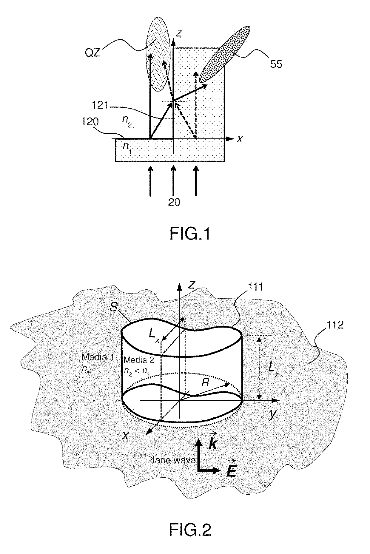
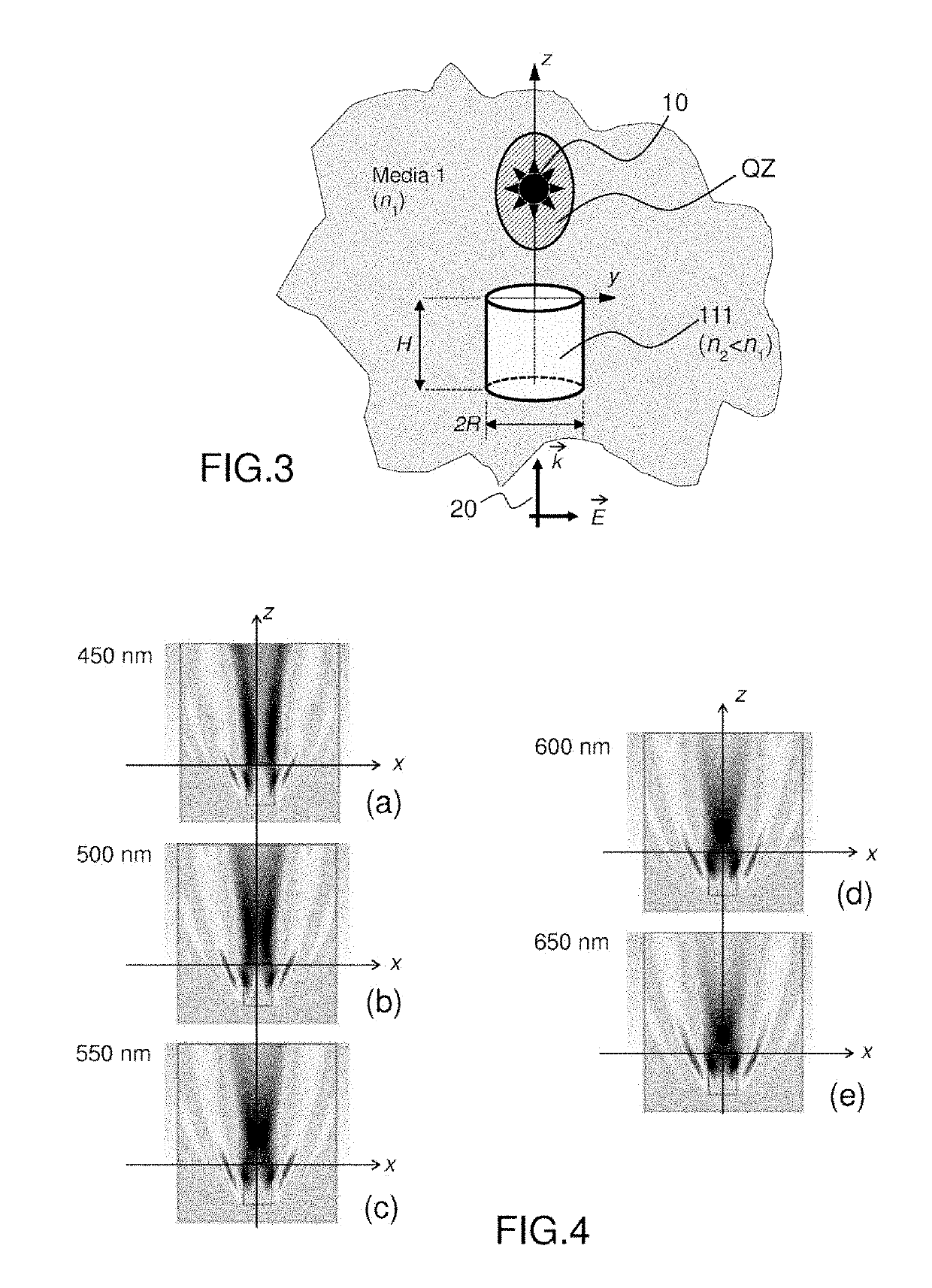
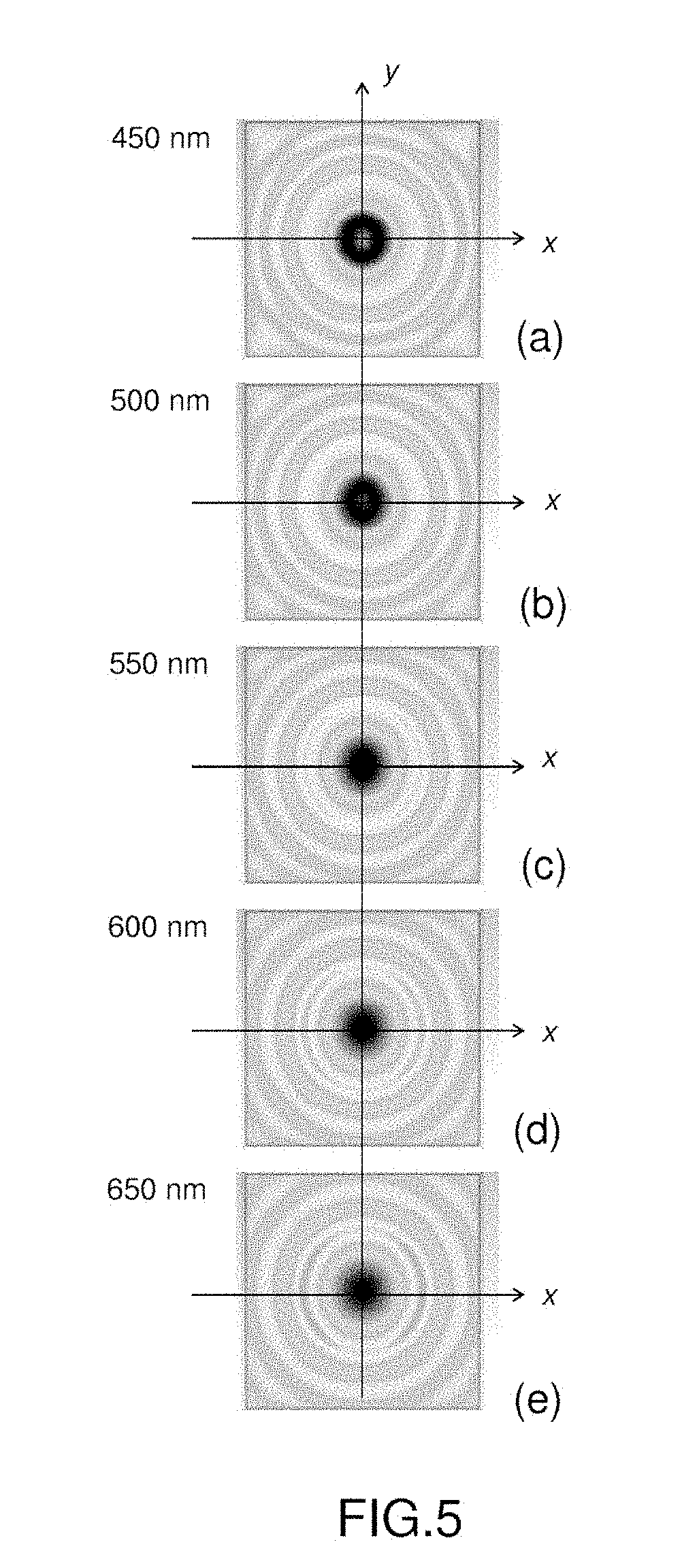
[0112]The general principle of the present disclosure relies on the design of a new dielectric microstructure, which may be used for shielding sub-wavelength-scale objects, or sub-wavelength-scale parts of larger objects, from electromagnetic waves incident on the microstructure from a given direction and within a given wavelength range. Its use is not limited to optical wavelengths. A step of refractive index in the dielectric microstructure gives rise to a diffraction phenomenon, which is in turn coupled to refraction and interference phenomena, and allows generating both quiet zones, in which the electromagnetic field intensity is below a threshold, and condensed beam(s) of radiation in the near zone when the dielectric microstructure is illuminated by a plane wave, depending on the shape and dimensions of the structure.

[0113]By placing the sub-wavelength-scale objects in a quiet zone, it is thus possible to shield them from incident electromagnetic waves. The formation of one or...


PUM


Abstract

A device for shielding at least one sub-wavelength-scale object from an electromagnetic wave, which is incident on said device, comprises at least one layer of a dielectric material, a surface of which having at least one abrupt change of level forming a step. At least a lower and lateral part of the surface with respect to the step is in contact with a medium having a refractive index lower than that of the dielectric material. The at least one sub-wavelength-scale object is located within the device in a quiet zone where an electromagnetic field intensity is below a threshold, the quiet zone extending above said surface, in the vicinity of the step, in a direction of incidence of said electromagnetic wave.

Description

1. TECHNICAL FIELD[0001]The present disclosure relates to a technique for shielding objects from electromagnetic waves. More precisely, it relates notably to techniques for shielding objects which dimensions are smaller than the wavelength of incident electromagnetic waves, also called sub-wavelength-scale objects, from such electromagnetic waves.[0002]Such techniques find application in a wide range of domains, such as displays (TV smartphones, tablets), augmented reality (AR) glasses, digital image sensors, etc.2. BACKGROUND[0003]This section is intended to introduce the reader to various aspects of art, which may be related to various aspects of the present disclosure that are described and / or claimed below. This discussion is believed to be helpful in providing the reader with background information to facilitate a better understanding of the various aspects of the present disclosure. Accordingly, it should be understood that these statements are to be read in this light, and no...

Claims


Application Information

Patent Timeline
IPC IPC(8): G02B5/20H05K9/00
CPCG02B5/203H05K9/0081G02B2207/121G02B2207/101G02B27/56
Inventor BORISKIN, ARTEMDAMGHANIAN, MITRABLONDE, LAURENT
Owner INTERDIGITAL CE PATENT HLDG
Why Eureka
Try Eureka