Alignment system and method

Active Publication Date: 2019-08-15
NEDERLANDSE ORG VOOR TOEGEPAST-NATUURWETENSCHAPPELIJK ONDERZOEK (TNO)
View PDF3 Cites 0 Cited by
  • Summary
  • Abstract
  • Description
  • Claims
  • Application Information

AI Technical Summary

Benefits of technology

[0015]The substrate can be held by a wafer stage, wherein the wafer stage is configured to move the wafer along a surface direction i.e. transverse to the distance between the lens and the wafer. The system provides the particular advantage of keeping the first object at the controlled distance from the second object while moving the first object over the surface of the second object. More particularly the lithographic apparatus can be configured to keep the lens at a controlled distance from the wafer while moving the lens over the surface of the wafer. For example, the distance between the lens and wafer can be very small, e.g. in the range of one to hundred nanometer.
[0016]Another or further aspect of the present disclosure provides a method of aligning a first object at a controlled distanced with respect to a second object. The method comprises providing an object stage to hold a surface of the first object at a distance over a surface of the second object; providing an object stage act

Problems solved by technology

However, optical techniques are typically substrate dependent, e.g. affected by the reflection behavior of the substrate material.
However, the system comprises a complicated gas system and may affect vacuum conditions.
Also the resolution may still be insufficient and the system r

Method used


Image

  • Alignment system and method
  • Alignment system and method
  • Alignment system and method

Examples


Example

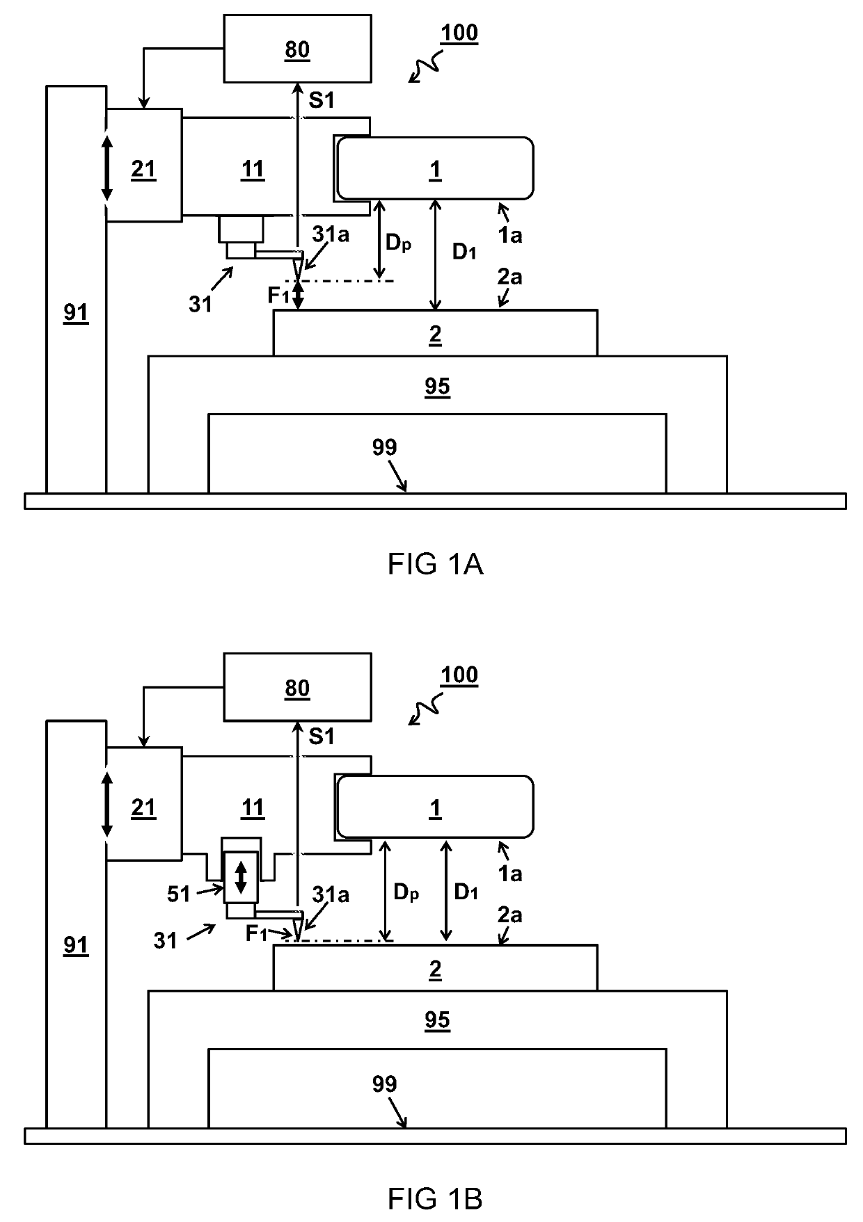
[0030]FIG. 1A schematically illustrates a first embodiment of an alignment system 100 for keeping a first object 1 at a controlled distanced D1 with respect to a second object 2.

[0031]In the embodiment, the system 100 comprises an object stage 11 configured to hold a surface 1a of the first object 1 at a distance D1 over a surface 2a of the second object 2. An object stage actuator 21 is configured to actuate the object stage 11 to vary the distance D1 between the surfaces 1a,2a of the first and second objects 1,2. A sensor device 31 comprising a probe tip 31a is connected at a predetermined probe level distance Dp relative to the surface 1a of the first object 1, in use, held by the object stage 11. The probe tip 31a is configured to perform an atomic force measurement AFM of a force F1 exerted via the probe tip 31a on a surface 2a of the second object 2.

[0032]In one embodiment, a controller 80 configured to control the object stage actuator 21 as a function of the measured force F...

Example

[0035]FIG. 1B schematically illustrates a second embodiment of an alignments system 100 with adjustable probe level distance Dp.

[0036]In the embodiment, the sensor device 31 comprising the probe tip 31a is connected to the object stage 11 via a sensor stage 51, wherein the sensor stage 51 comprises an actuator configured to variably set the probe level distance Dp between a level of the probe tip 31a and a level of the surface 1a of the first object 1. For example, the probe level distance Dp is measured transverse to the surface 2a of the second object 2. In another or further embodiment, the probe level distance Dp is set as a function of a desired distance D1 between the first object 1 and second object 2.

[0037]In one embodiment, the probe level distance Dp between the first object 1 and the probe tip 31a is set close or equal to the desired distance D1 between the first object 1 and second object 2, e.g. within a margin of less than one micrometre, less than hundred nanometres, ...

Example

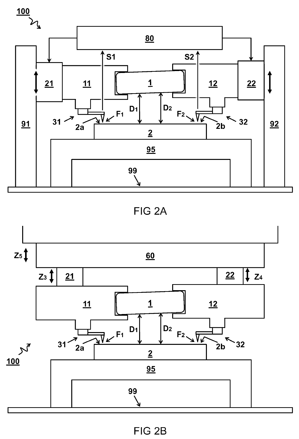
[0039]FIG. 2A schematically illustrates a third embodiment of an alignments system 100 with multiple sensor devices.

[0040]In one embodiment, the system 100 comprises at least two sensor devices 31,32 each configured to measure a force F1,F2 between a respective probe tip 31a,32a and different parts 2a,2b of the surface 2a of the second object 2. In another or further embodiment, the system comprises one or more object stage actuators 21,22 configured to control respective distances D1,D2 between the first object 1 and the different parts 2a,2b of the surface of the second object 2. In another or further embodiment, the one or more object stage actuators 21,22 are configured to control a distance and tilt of the first object 1 with respect to the surface 2a,2b of the second object 2.


PUM


Abstract

An alignment system (100) and method for positioning and/or keeping a first object (1) at a controlled distanced (D1) with respect to a second object (2). An object stage (11) is configured to hold a surface (1a) of the first object (1) at a distance (D1) over a surface (2a) of the second object (2). A sensor device (31) comprising a probe tip (31a) is connected at a predetermined probe level distance (Dp) relative to the surface (1a) of the first object (1). The probe tip (31a) is configured to perform an atomic force measurement (AFM) of a force (F1) exerted via the probe tip (31a) on a surface (2a) of the second object (2). A controller (80) is configured to control an object stage actuator (21) as a function of the probe level distance (Dp) and the measured force (F1) to maintain the controlled distanced (D1).

Description

TECHNICAL FIELD AND BACKGROUND[0001]The present disclosure relates to an alignment system and method for positioning and / or keeping a first object at a controlled distanced with respect to a second object.[0002]In nano-manufacturing and metrology, it is often desired to have an optical element accurately positioned with respect to a substrate, e.g. wafer. Typically, a measurement is done initially with a level sensor, which maps the height of a target substrate, followed by the optical element being positioned based on the level sensing measurement. For example, in a lithographic apparatus an imaging lens can be used to project an image onto a wafer. To maintain focus, it is desired to keep a controlled distance between the imaging lens and the wafer. However, at high resolutions, even minute variations in the thickness, tilting, or waviness of the wafer can have a significant influence on the focus, e.g. while moving the wafer under the lens. Accordingly, it is desired to constantl...

Claims


Application Information

Patent Timeline
IPC IPC(8): G03F9/00G01Q20/02G01Q60/24G01Q40/00
CPCG03F9/7065G01Q20/02G01Q60/24G01Q40/00G01Q10/065G01Q30/02G01Q70/06G03F9/7023G03F9/7061
Inventor SADEGHIAN MARNANI, HAMED
Owner NEDERLANDSE ORG VOOR TOEGEPAST-NATUURWETENSCHAPPELIJK ONDERZOEK (TNO)
Why Eureka
Try Eureka