Tensioner

a technology of tensioner and oil pressure chamber, which is applied in the direction of belt/chain/gearing, mechanical equipment, belts/chains/gearings, etc., can solve the problems of increasing the power of the oil pressure generation source, the difficulty of stabilizing the oil pressure in the oil pressurizing chamber b>511/b>, and the increase of so as to reduce the amount of oil consumption, prevent the occurrence of trouble, and reduce the size of power

Active Publication Date: 2019-08-22
TSUBAKIMOTO CHAIN CO
View PDF0 Cites 4 Cited by
  • Summary
  • Abstract
  • Description
  • Claims
  • Application Information

AI Technical Summary

Benefits of technology

[0012]In addition, unlike in an existing tensioner provided with a relief mechanism, it is possible to prevent oil from being partly released to the outside. This can reduce an amount of oil consumption and reduce the size of a power of an oil pressure generation source. In addition, it is also possible to prevent oil in the oil pressurizing chamber from gradually leaking to the outside at the time of engine stop when a supply of the oil to the tensioner stops. Therefore, it is possible to maintain the amount of the oil in the oil pressurizing chamber for a long period of time and prevent the occurrence of trouble such as the occurrence of abnormal noise at the time of re-operation of the engine.
[0013]Moreover, by configuring the pressure adjustment unit separate from the housing and the plunger, the need to consider influence on the basic function of the tensioner is reduced and restrictions on the design of the unit case and the moving member, such as the materials and sizes thereof, are reduced. Accordingly, it is possible to easily increase a change in the capacity of the oil pressurizing chamber resulting from the movement of the moving member and improve a pressure adjusting function such as the ability to accurately and easily maintain the liquid tight state between the unit case and the moving member. During the assembly of the tensioner, it is sufficient to attach the pressure adjustment unit to the housing or the plunger. This can reduce the burden of assembling the tensioner and facilitates a change in the design of the pressure adjustment unit and the adjustment thereof.
[0014]In accordance with another aspect of the present invention, a piston section of the moving member is slidably disposed in a cylinder section formed in the unit case. This allows a change in the capacity of the oil pressurizing chamber to be easily increased in accordance with the amount of the movement of the moving member using a simple configuration. In addition, the liquid tight state between the cylinder section and the piston section can easily and accurately be maintained.
[0015]In a

Problems solved by technology

As a result, a problem arises in that the oil pressure in the oil pressurizing chamber 511 is hard to stabilize.
Consequently, a problem

Method used


Image

  • Tensioner
  • Tensioner
  • Tensioner

Examples


first embodiment

[0024]The following will describe a tensioner 10 according to the present invention on the basis of the drawings.

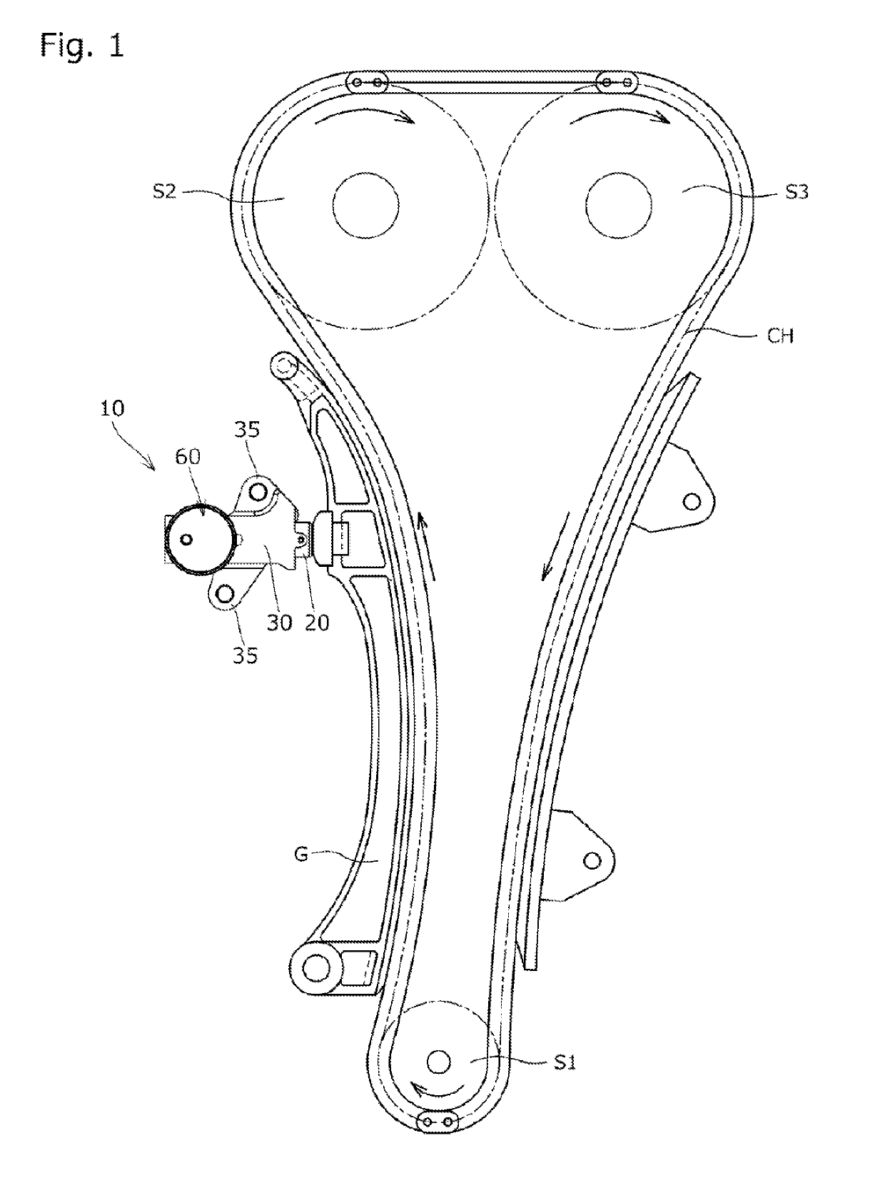
[0025]First, the tensioner 10 is embedded in a chain transmission device used for a timing system in an automobile engine or the like. As shown in FIG. 1, the tensioner 10 is attached to an engine block (not shown) to give an appropriate tension, via a tensioner lever G, to the loose side of a transmission chain CH wound around a plurality of sprockets S1 to S3 and inhibit vibration from occurring during driving.

[0026]As shown in FIG. 4, the tensioner 10 includes a plunger 20 having a cylindrical plunger hole 21 that is rearwardly opened, a housing 30 having a plunger container hole 31 that is forwardly opened to contain the plunger 20, a main spring (main biasing unit) 40 extensively contained in an oil pressurizing chamber 11 formed between the plunger 20 and the plunger container hole 31 to forwardly bias the plunger 20, a check valve 50 which partitions the space betw...

second embodiment

[0073]Also, in the second embodiment, as shown in FIG. 5, in the bottom section (front end section) of the plunger 20, a unit opening 23 is formed to extend from the plunger hole 21 to the outer wall of the plunger 20 through the plunger 20.

[0074]In the vicinity of the front end of the plunger 20, a convex section 24 is formed to annularly protrude from the inner peripheral surface of the plunger hole 21 in a radially inward direction and restrict rearward movement of the unit case 61 relative to the plunger 20.

[0075]In the inner peripheral surface of the plunger hole 21 located on the front side of the convex section 24, a concave section 25 is formed by annularly concaving the inner peripheral surface of the plunger hole 21.

[0076]The main spring 40 is formed of a metal or the like. As shown in FIG. 5, the main spring 40 is extensively contained in the oil pressurizing chamber 11 to have one end in contact with the convex section 24 of the plunger 20 and the other end in contact wi...


PUM


Abstract

Provided is a tensioner capable of stabilizing an oil pressure in an oil pressurizing chamber. The tensioner includes a pressure adjustment unit. The pressure adjustment unit includes a unit case attached to the housing or the plunger, a moving member disposed in the case inner space to be capable of moving closer to and farther away from the oil pressurizing chamber, and a pressure adjustment biasing unit which biases the moving member toward the oil pressurizing chamber. A gap between an inner wall of the case inner space and the moving member is configured to be held in a liquid tight state at any position between a position where the moving member is closest to the oil pressurizing chamber as a result of moving and a position where the moving member is most distant from the oil pressurizing chamber.

Description

BACKGROUND OF THE INVENTION1. Field of the Invention[0001]The present invention relates to a tensioner which gives an appropriate tension to a traveling chain, belt, or the like.2. Description of the Related Art[0002]Conventionally, a tensioner has been used commonly to allow a chain or the like to retain an appropriate tension. For example, a known tensioner is used in a chain guide mechanism which uses a tensioner lever to slidably guide a transmission chain such as a roller chain endlessly wound between respective sprockets provided around a crank shaft and a camshaft in an engine. To allow a chain or the like to retain an appropriate tension, the chain guide mechanism uses the tensioner to bias the tensioner lever.[0003]As a known tensioner used in such a chain guide mechanism, a tensioner 510 is known which includes a plunger 520 having a plunger hole 521 that is rearwardly opened, a housing 530 having a plunger container hole 531 that is forwardly opened to contain the plunger...

Claims


Application Information

Patent Timeline
IPC IPC(8): F16H7/08
CPCF16H7/0848F16H2007/0814F16H2007/0806F16H2007/0859F16H7/08F16H2007/0812F16H2007/0893
Inventor WATANABE, MASANORI
Owner TSUBAKIMOTO CHAIN CO
Why Eureka
Try Eureka