Adjusting a field distribution of an antenna arrangement of a magnetic resonance system

a magnetic resonance system and field distribution technology, applied in the field of adjusting the field distribution of the antenna arrangement of the magnetic resonance system, can solve the problems of impaired symmetry of the field distribution, and achieve the effects of increasing the symmetry or homogeneity of the field distribution in the antenna arrangement, increasing the capacitive coupling, and increasing the symmetry or homogeneity of the field distribution

Active Publication Date: 2019-08-22
SIEMENS HEALTHCARE GMBH
View PDF0 Cites 0 Cited by
  • Summary
  • Abstract
  • Description
  • Claims
  • Application Information

AI Technical Summary

Benefits of technology

[0017]One oscillating circuit antenna element out of the multiple oscillating circuit antenna elements may, for example, include a capacitor. The capacitor is coupled to the antenna arrangement by the assigned switching element in order to change the capacitance of the antenna arrangement in order to increase the symmetry or homogeneity of the field distribution in the antenna arrangement. For example, a capacitor may be arranged in series with the assigned switching element between two galvanically isolated elements of a ferrule in order to increase the capacitive coupling between the galvanically isolated elements of the ferrule in dependence on the switching status of the switching element. Depending on the asymmetry or inhomogeneity of the field distribution, increasing the capacitive coupling in this way may improve the symmetry or homogeneity of the field distribution.
[0018]Alternatively or additionally, one oscillating circuit antenna element out of the multiple oscillating circuit antenna elements may, for example, include an inductive element. The inductive element is coupled to the antenna arrangement by the assigned switching element in order to change the inductance of the antenna arrangement in order to increase the symmetry or homogeneity of the field distribution. For example, a series circuit consisting of the inductive element and the assigned switching element may be arranged parallel to one of the longitudinal rods of an antenna with a birdcage structure. This arrangement enables the inductance of the longitudinal rod to be increased in dependence on the switching status of the switching element. Increasing t

Problems solved by technology

A symmetry of the field distribution may be impaired by positional inaccuracy of the antenna arrangement in the magnetic resonance system.
For example,

Method used


Image

  • Adjusting a field distribution of an antenna arrangement of a magnetic resonance system
  • Adjusting a field distribution of an antenna arrangement of a magnetic resonance system
  • Adjusting a field distribution of an antenna arrangement of a magnetic resonance system

Examples


Embodiment Construction

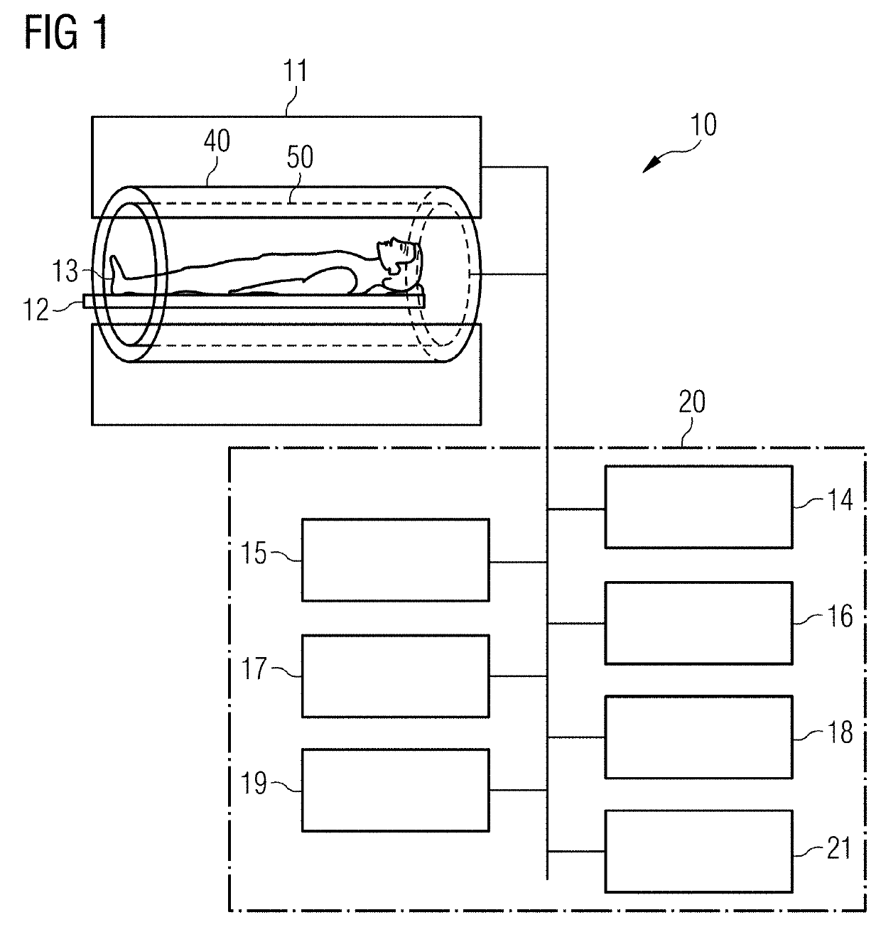
[0040]FIG. 1 is a schematic representation of one embodiment of a magnetic resonance (MR) system 10. The magnetic resonance system 10 includes a magnet 11 for the generation of a polarization field B0. A person to be examined 13 lying on a bench 12 may be moved into a cylindrical bore in the magnet 11 for the recording spatially encoded magnetic resonance signals or MR data from the person to be examined 13. A cylindrical antenna arrangement 50 is provided around the cylindrical bore in order to generate radio-frequency signals (e.g., radio-frequency (RF) pulses). To provide a defined environment for field generation by the antenna arrangement 50, a cylindrical radio-frequency screen 40 is provided around the antenna arrangement 50. The irradiation of radio-frequency pulses with the antenna arrangement 50 and switching of magnetic field gradients may cause the magnetization generated by the polarization field B0 to be deflected out of the equilibrium position and spatially encoded, ...


PUM


Abstract

A method for adjusting a field distribution of an antenna arrangement of a magnetic resonance system is provided. The symmetry of the field distribution may be impaired by positional inaccuracy of the antenna arrangement in the magnetic resonance system. The antenna arrangement comprises oscillating circuit antenna elements and switching elements. Each of the oscillating circuit antenna elements is assigned a respective switching element of the switching elements. A respective switching element is configured to couple the assigned oscillating circuit antenna element operatively to the antenna arrangement in dependence on a status of the respective switching element. During the method, symmetry information on the field distribution in the antenna arrangement is measured, and the switching elements are automatically adjusted using the measured symmetry information, such that the symmetry of the field distribution in the interior of the antenna arrangement is increased.

Description

[0001]This application claims the benefit of EP 18157877.4, filed on Feb. 21, 2018, which is hereby incorporated by reference in its entirety.BACKGROUND[0002]The present embodiments relate to adjusting a field distribution of an antenna arrangement of a magnetic resonance system.[0003]In magnetic resonance (MR) systems, antenna arrangements may be used to generate a radio-frequency field (e.g., a B1 field). Such antenna arrangements may, for example, have a cylindrical or tubular structure arranged around a patient receiving bore of the magnetic resonance system. Examples of antenna arrangements (e.g., body coils) are described in the publications U.S. Pat. Nos. 8,362,775 B2, 6,781,378 B2, 8,072,218 B2, and US 20170016969 A1.[0004]Alternatively, such an antenna arrangement may also be provided in conjunction with a local coil. The antenna arrangement may include an actual antenna (e.g., a birdcage antenna or a transverse electromagnetic (TEM) resonator (e.g., TEM antenna) and a radi...

Claims


Application Information

Patent Timeline
IPC IPC(8): G01R33/36G01R33/58G01R33/10G01R33/34
CPCG01R33/3664G01R33/583G01R33/10G01R33/34076A61B5/055G01R33/34046G01R33/422G01R33/5659
Inventor NISTLER, JÜRGENLAZAR, RAZVAN
Owner SIEMENS HEALTHCARE GMBH
Why Eureka
Try Eureka