Eureka AIR delivers breakthrough ideas for toughest innovation challenges, trusted by R&D personnel around the world.

Tunable light projector

Active Publication Date: 2019-08-22
LIQXTAL TECH
View PDF4 Cites 4 Cited by
  • Summary
  • Abstract
  • Description
  • Claims
  • Application Information

AI Technical Summary

Benefits of technology

The patent describes a new type of projector that uses a special liquid crystal lens to change the focus of a beam of light. This allows the projector to project in focus over a wider range of distance. The use of this liquid crystal lens also allows for the creation of a small optical sensor. The patent also mentions the use of a tunable liquid crystal panel that can switch between a structured light and a flood light, making it more cost-effective and space-efficient for devices that require both functions.

Problems solved by technology

Structured illumination is limited by having projection lens with fixed focal length, which limits the distance that a clear and focused diffraction pattern are able to form, ultimately limiting the distance of an object that is resolvable to be within a small range.
However, such a method comes at the expense of light efficiency, 2D diffraction pattern points and resolution.
However, adopting two systems, i.e. the flood light system and the structured light system, in a mobile device may occupy large space and be costly.

Method used


Image

  • Tunable light projector
  • Tunable light projector
  • Tunable light projector

Examples


Embodiment Construction

[0041]Reference will now be made in detail to the present preferred embodiments of the invention, examples of which are illustrated in the accompanying drawings. Wherever possible, the same reference numbers are used in the drawings and the description to refer to the same or like parts.

[0042]Further, spatially relative terms, such as “underlying”, “below”, “lower”, “overlying”, “upper”, “top”, “bottom”, “left”, “right” and the like, may be used herein for ease of description to describe one element or feature's relationship to another element(s) or feature(s) as illustrated in the figures. The spatially relative terms are intended to encompass different orientations of the device in use or operation in addition to the orientation depicted in the figures. The apparatus may be otherwise oriented (rotated 90 degrees or at other orientations) and the spatially relative descriptors used herein may likewise be interpreted accordingly.

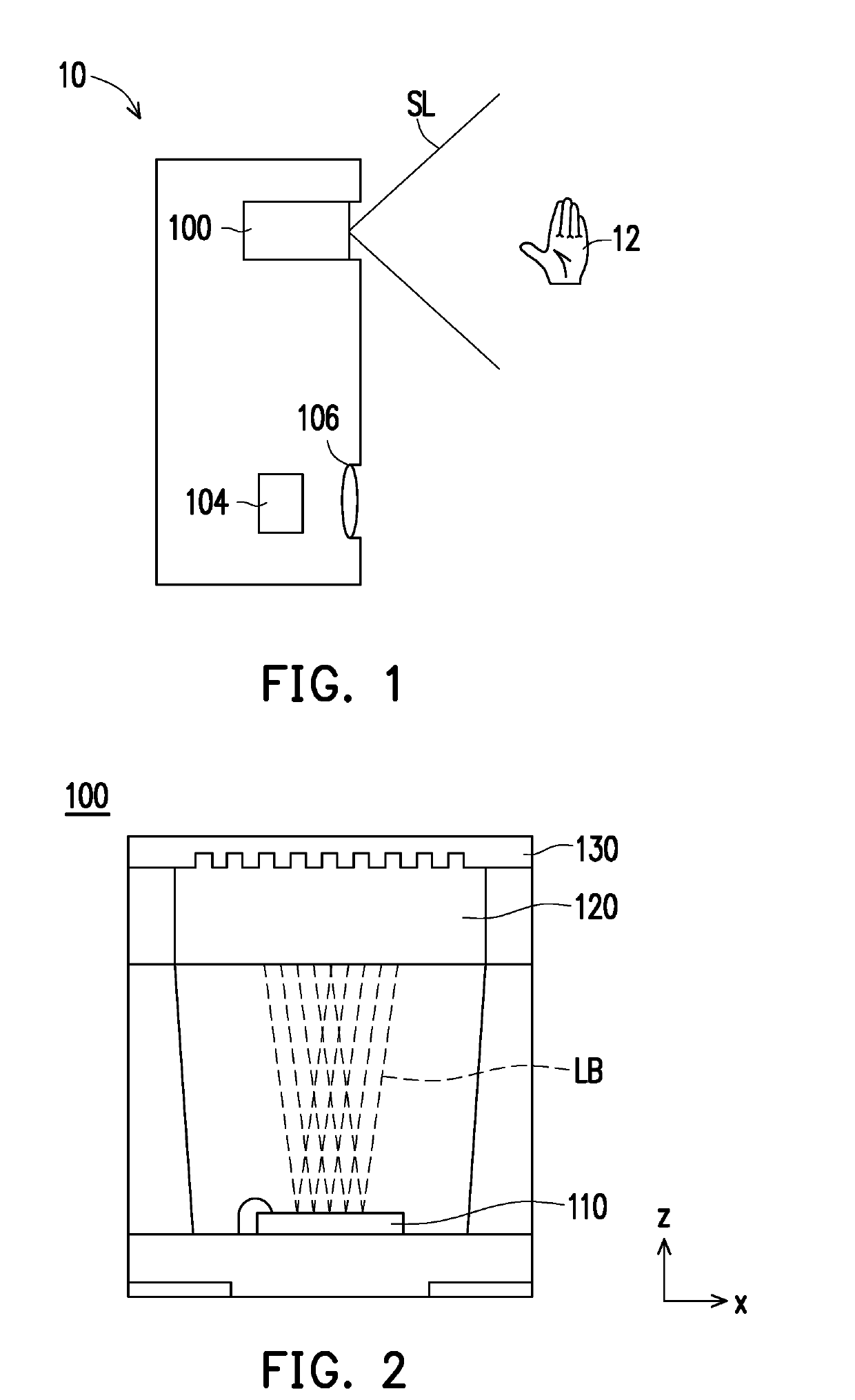
[0043]FIG. 1 is a schematic cross-sectional view of an...


PUM


Abstract

A tunable light projector including a light source, a fixed optical phase modulator, a tunable liquid crystal panel, and a driver is provided. The light source is configured to emit a light beam. The fixed optical phase modulator is disposed on a path of the light beam and configured to modulate phases of the light beam. The tunable liquid crystal panel is disposed on the path of the light beam from the fixed optical phase modulator and configured to switch the light beam between a structured light and a flood light. The driver is electrically connected to a first electrode layer and a second electrode layer of the tunable liquid crystal panel and configured to change a voltage difference between the first electrode layer and the second electrode layer, so as to switch the light beam between the structured light and the flood light.

Description

CROSS-REFERENCE TO RELATED APPLICATION[0001]This application is a continuation-in-part application of and claims the priority benefit of U.S. application Ser. No. 16 / 044,484, filed on Jul. 24, 2018, now pending, which claims the priority benefit of U.S. provisional application Ser. No. 62 / 566,538, filed on Oct. 2, 2017. This application also claims the priority benefit of U.S. provisional application Ser. No. 62 / 804,757, filed on Feb. 13, 2019. The entirety of each of the above-mentioned patent applications is hereby incorporated by reference herein and made a part of this specification.BACKGROUNDTechnical Field[0002]The invention generally relates to a sensing device and a light projector, and, in particular, to an optical sensing device, a structured light projector, and a tunable light projector.Description of Related Art[0003]At present, the mainstream technology in the field of 3-dimension (3D) sensing is divided into time of flight (TOF) and structured illumination. The TOF te...

Claims


Application Information

Patent Timeline
IPC IPC(8): G02F1/29G01S7/481
CPCG02F2201/122G02F2001/294G01S17/42G01S7/4814G02F1/29G01B11/2513G02F1/294
Inventor CHEN, HUNG-SHANCHEN, MING-SYUAN
Owner LIQXTAL TECH
Why Eureka
Eureka Blog
Learn More