
Multistage centrifugal grinder pump

a centrifugal grinder and multi-stage technology, applied in the direction of non-positive displacement pumps, radial flow pumps, fluid engines, etc., can solve the problems of reducing efficiency, hydraulic efficiency, servicing or expensive maintenance work, etc., and achieve the effect of avoiding or at least significantly reducing the risk of clogging the pump

Active Publication Date: 2019-08-29
SULZER MANAGEMENT AG
View PDF1 Cites 0 Cited by
  • Summary
  • Abstract
  • Description
  • Claims
  • Application Information

AI Technical Summary

Benefits of technology

The invention proposes a compact and efficient multistage centrifugal grinder pump that can generate a high head, without the risk of clogging. The pump has a unique design with an internal stationary diffusor for guiding the fluid conveyed by the first stage impeller to the second stage impeller. The diffusor has a semi-open design with no partition protruding beyond the first stage impeller, which prevents solid constituents from collecting or sticking and increases the efficiency of the pump. The design of the pump is further simplified by having circular cross-sections for the first and second chambers. The top wall of the diffusor has grooves for cleaning out solid constituents, further reducing the risk of clogging.

Problems solved by technology

In the conveying of sewage or waste water and in particular of domestic waste water, problems result because such liquids contain constituents such as fibrous materials, cloths, textiles, rags, plastic bags or other solids which can very easily become stuck in the region of the pump and can then result in a reduction in the efficiency, in particular the hydraulic efficiency, of the pump up to the complete blocking of the impeller of the pump and can cause servicing or also complex and / or expensive maintenance work.
However, if gravity is not sufficient to move the sewage to the desired location or if gravity based systems are not economical, grinder pumps are used to lift the sewage or to convey the sewage over longer distances.
Such a high head in combination with a reasonable flow rate of e.g. up to 7 m3 / h is at least very difficult if not impossible to realize with a centrifugal grinder pump having only one impeller.
This overall design has the disadvantage to require quite a lot of space.

Method used


Image

  • Multistage centrifugal grinder pump
  • Multistage centrifugal grinder pump
  • Multistage centrifugal grinder pump

Examples


Embodiment Construction

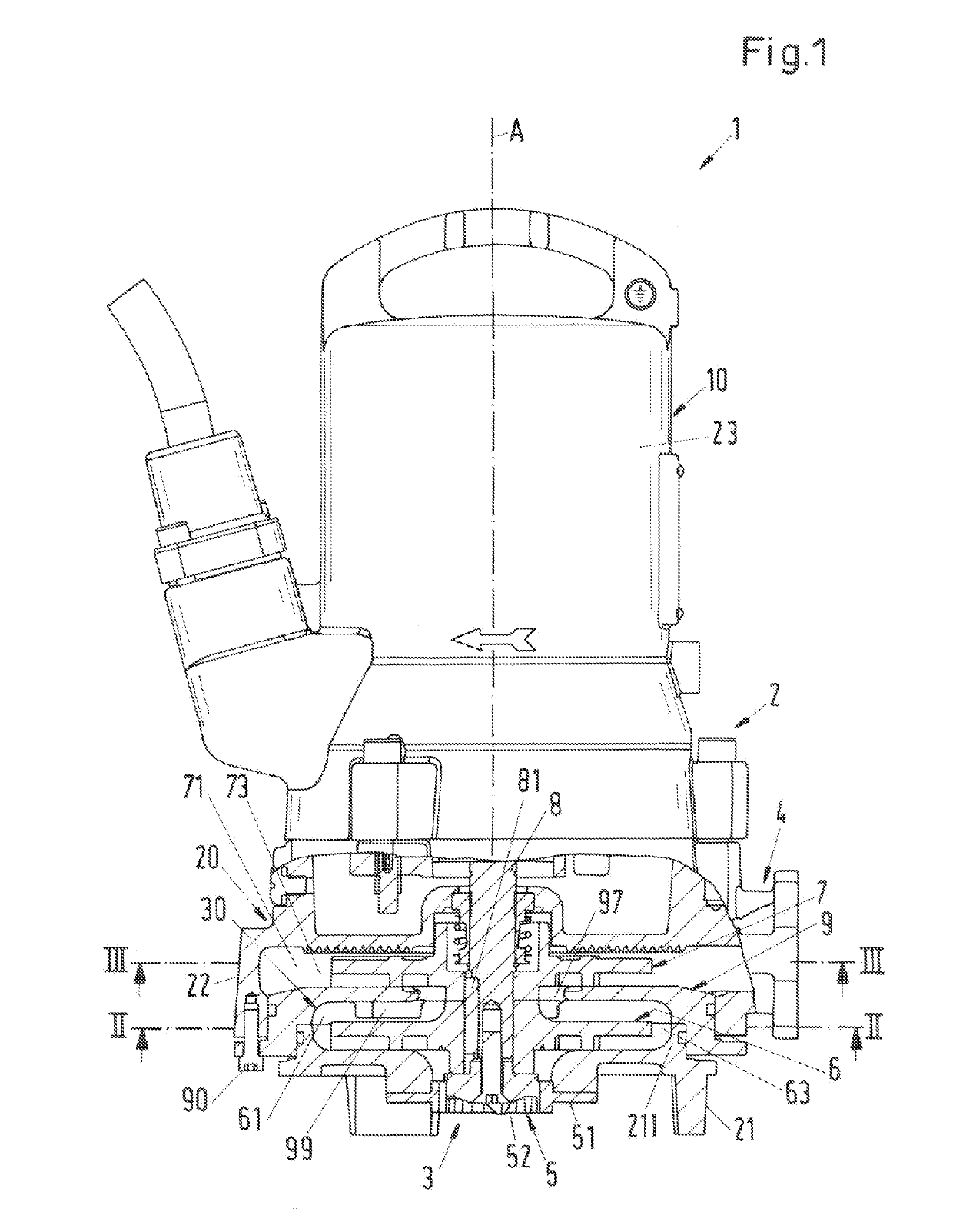
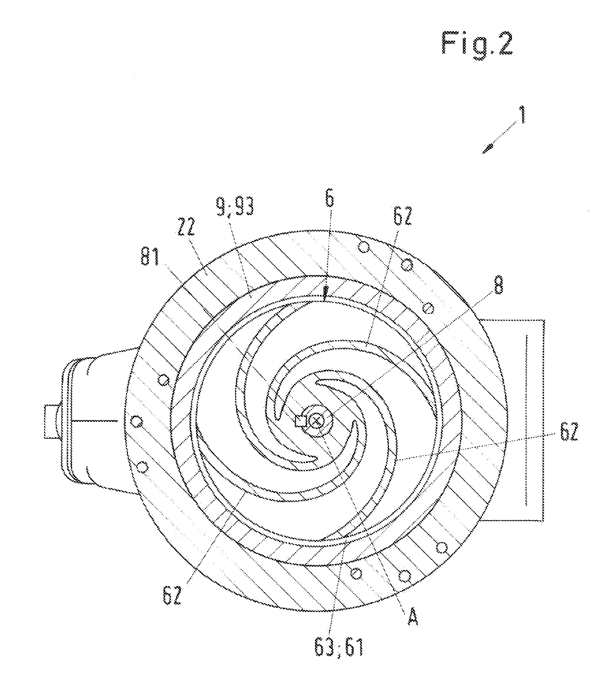
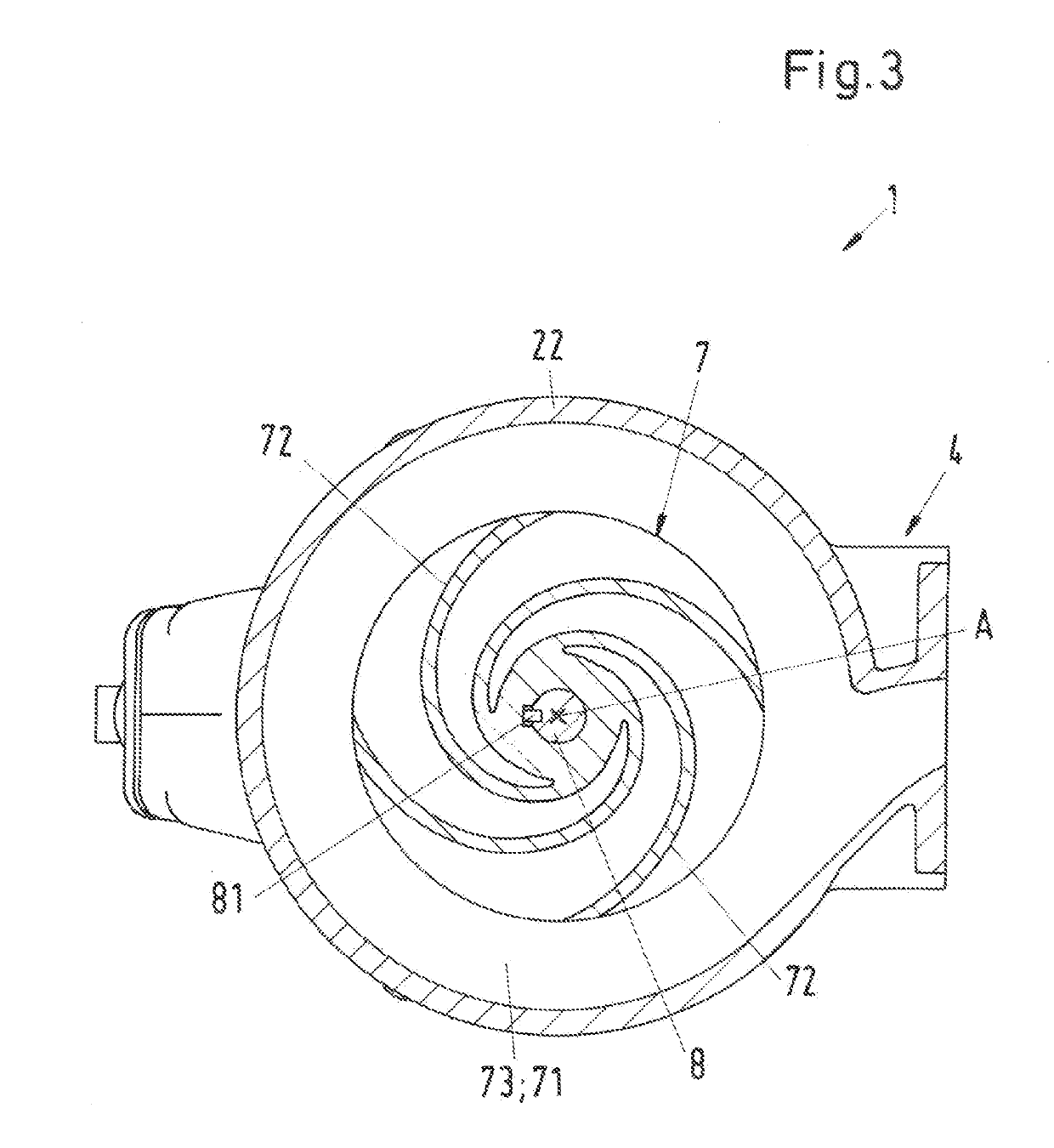
[0040]In the following description reference is made by way of example to the important application that the multistage centrifugal grinder pump is used for conveying sewage or wastewater in private, municipal or industrial areas. The sewage typically comprises solid constituents such as fibrous materials, cloths, textiles, rags, paper, plastic bags or other solids. FIG. 1 shows an overall view of an embodiment of a multistage centrifugal grinder pump according to the invention which is designated in its entity with reference numeral 1. This embodiment is configured as a two stage pump 1. The pump 1 comprises a housing 2, in which a pump unit 20 and a drive unit 10 are arranged. FIG. 1 is a break-out section view showing the pump unit 20 in a cross-sectional view and the rest of the centrifugal pump 1 in a view on the housing 2 of the pump 1.

[0041]The housing 2 has a pump inlet 3 for a fluid to be conveyed and a pump outlet 4 for discharging the fluid. The fluid is for example sewag...


PUM


Abstract

A multistage centrifugal grinder pump includes a grinder to grind a fluid, a first stage impeller, a second stage impeller, a stationary diffusor arranged between the first stage impeller and the second stage impeller to guide the fluid from the first stage impeller to the second stage impeller and a shaft to rotate the first stage impeller, the second stage impeller and the grinder. The first and second stage impellers in series and connected to the shaft in a torque-proof manner. The diffusor is a semi-open diffusor having a top wall, a radially outer annular side wall, and an open bottom side facing the first stage impeller, the top wall arranged adjacent the second stage impeller, the top wall having a central outlet opening surrounding the shaft, and the open bottom side extending beyond the first stage impeller with respect to a radial direction.

Description

CROSS-REFERENCE TO RELATED APPLICATION[0001]This application claims priority to European Application No. 18158444.2, filed Feb. 23, 2018, the contents of which are hereby incorporated herein by reference.FIELD OF THE INVENTION[0002]The invention relates to a multistage centrifugal grinder pump.BACKGROUND OF THE INVENTION[0003]In the conveying of sewage or waste water and in particular of domestic waste water, problems result because such liquids contain constituents such as fibrous materials, cloths, textiles, rags, plastic bags or other solids which can very easily become stuck in the region of the pump and can then result in a reduction in the efficiency, in particular the hydraulic efficiency, of the pump up to the complete blocking of the impeller of the pump and can cause servicing or also complex and / or expensive maintenance work. Special measures therefore have to be taken with such pumps in order to effectively prevent clogging. A known solution to address this problem are c...

Claims


Application Information

Patent Timeline
Patent Type & Authority Applications(United States)
IPC IPC(8): F04D1/06F04D29/42F04D7/04
CPCF04D1/06F04D7/045F04D29/426F04D1/08F04D29/445B02C18/0092B02C18/10F04D29/448
Inventor BURKE, MICHAELCULLEN, IAN
Owner SULZER MANAGEMENT AG
Learn More