
Expansion Joint Seal with Positioned Load Transfer Member

a load transfer member and expansion joint technology, applied in the direction of unauthorized memory use protection, instruments, etc., can solve the problems of system lack of seismic movement, system lack of resiliency and seismic movement required in expansion joints, and damage to joints, etc., to facilitate compression or positioning of structural members, facilitate instruction, and resist upward deflection

Active Publication Date: 2019-08-29
SCHUL INT CO LCC
View PDF0 Cites 36 Cited by
  • Summary
  • Abstract
  • Description
  • Claims
  • Application Information

AI Technical Summary

Benefits of technology

The present invention provides an expansion joint design that is easy to install and resistant to upward deflection during installation. The expansion joint system includes an elongated core of compressible material and one or more incompressible load-transfer members bonded to or integrated into the core. The technical effects of the invention include facilitating instruction and easy positioning of structural members in the expansion joint body.

Problems solved by technology

Moreover, these joints are subject to damage over time.
Most damage is from vandalism, wear, environmental factors and when the joint movement is greater, the seal may become inflexible, fragile or experience adhesive or cohesive failure.
These systems lack the resiliency and seismic movement required in expansion joints.
These systems have been further limited in functioning as a fire-resistant barrier, which is often a desired function.
Other systems have incorporated cover plates that span the joint itself, often anchored to the concrete or attached to the expansion joint material and which are expensive to supply and install.
Additionally, cover plates that are higher than the deck or substrate level can present a hazard, such as tripping, an unnecessary impediment, such as to wheelchairs.
Further, these systems require undesirable mechanical attachment, which requires drilling into the deck or joint substrate.
Cover plate systems that are not mechanically attached rely on support or attachment to the expansion joint, thereby subject the expansion joint system to continuous compression, expansion and tension on the bond line when force is applied to the cover plate, which shortens the life of the joint system.

Method used


Image

  • Expansion Joint Seal with Positioned Load Transfer Member
  • Expansion Joint Seal with Positioned Load Transfer Member
  • Expansion Joint Seal with Positioned Load Transfer Member

Examples


Embodiment Construction

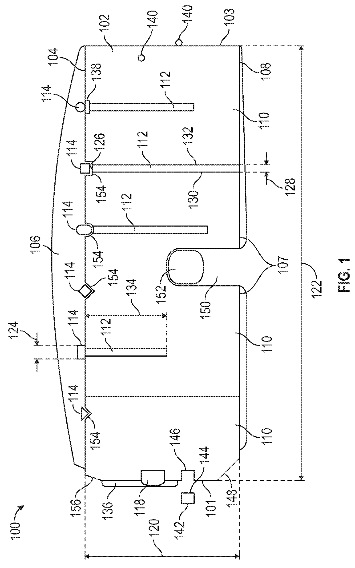
[0025]Referring to FIG. 1, an end view of one embodiment of the expansion joint system 100 of the present disclosure is provided. The system 100 includes an elongated core 102 and at least one longitudinal load-transfer member 114 which are bonded together. The system 100 provides an expansion joint system which can be used in standard applications and in exposed, high traffic areas, which is preferably water resistant.

[0026]The elongated core 102 is composed of resiliently compressible foam, which may be closed cell or open cell foam, or a combination thereof. The extent of compressibility may be selected based on the need. A higher compression is known to result in higher water resistance, but may create difficulties in installation. With as compression increases the elongated core 102 ultimately becomes so compressed as to lack flexibility or further compressibility, such as at a ratio of 5:1. The elongated core 102 may be compressible by 25%, or may compress by 100% or as high a...


PUM


Abstract

An expansion joint design for supporting transfer loads. The system includes an elongated core and at least one longitudinal load-transfer member which are bonded together.

Description

CROSS-REFERENCE TO RELATED APPLICATIONS[0001]This application is a continuation in part of U.S. patent application Ser. No. 16 / 213,273, filed Dec. 7, 2018, which is incorporated by reference, the benefit of which is hereby claimed, which is a continuation-in-part of U.S. patent application Ser. No. 16 / 012,457 for “Expansion Joint Seal with Load Transfer and Flexion, filed Jun. 19, 2018, which issued as U.S. Pat. No. 10,213,692 on Feb. 26, 2019, which is incorporated by reference, the benefit of which is hereby claimed, which is a continuation-in-part of U.S. patent application Ser. No. 15 / 885,028 for “Expansion Joint Seal with Surface Load Transfer and Intumescent, filed Jan. 31, 2018, now U.S. Pat. No. 10,066,386, which is incorporated by reference, the benefit of which is hereby claimed, which is a continuation in part of U.S. patent application Ser. No. 15 / 784,529 for “Expansion Joint Seal with Surface Load Transfer and Intumescent, filed Oct. 16, 2017, now U.S. Pat. No. 9,951,51...

Claims


Application Information

Patent Timeline
IPC IPC(8): G06F21/60H04L9/08G06F12/14G06F9/455
CPCG06F21/602H04L9/08G06F12/1425G06F12/1408G06F2221/0755G06F2009/45587G06F2221/0753G06F2212/1052G06F9/45558E04B1/6812E01C11/106E01C11/02E01C11/14E01D19/06E04B1/68E04B1/6801E04B1/948E04B1/62G06F21/107
Inventor ROBINSON, STEVEN R.
Owner SCHUL INT CO LCC
Features
  • Generate Ideas
  • Intellectual Property
  • Life Sciences
  • Materials
  • Tech Scout
  • Unparalleled Data Quality
  • Higher Quality Content
  • 60% Fewer Hallucinations
Learn More