

Thermoelectric conversion device
a technology of thermal conversion device and thermal conversion device, which is applied in the direction of thermoelectric device with peltier/seeback effect, electric apparatus, generator/motor, etc., can solve the problems of increasing the cost of material, affecting the research mainstream, and affecting the research
- Summary
- Abstract
- Description
- Claims
- Application Information
AI Technical Summary
Benefits of technology
Problems solved by technology
Method used
Image

Examples
first embodiment
[0039]Hereinafter, a thermoelectric conversion device 1 according to a first embodiment will be described with reference to the accompanying drawings.
(Basic Structure)
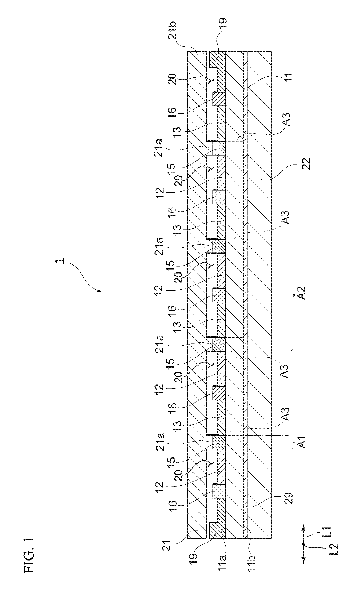
[0040]FIG. 1 is a cross-sectional view illustrating an example of the thermoelectric conversion device 1 according to the first embodiment.
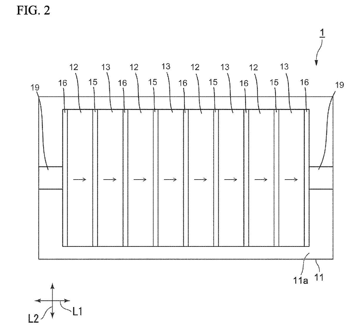
[0041]As illustrated in FIG. 1, the thermoelectric conversion device 1 according to this embodiment includes a substrate 11 including a first surface 11a and a second surface 11b which are opposite to each other in a thickness direction, a thermoelectric conversion film (a plurality of first thermoelectric conversion films 12 and a plurality of second thermoelectric conversion films 13) disposed on the first surface 11a, a first heat transfer part 22 having heat conductivity higher than heat conductivity of air, and a second heat transfer part 21 having heat conductivity higher than heat conductivity of air.
[0042]In this embodiment, the second heat transfer part 21 side along a thic...
second embodiment
[0113]Hereinafter, with regard to a thermoelectric conversion device 2 according to a second embodiment, description will be mainly given of a configuration different from that of the thermoelectric conversion device 1 according to the first embodiment, and description of a common configuration will be appropriately omitted.
[0114]FIG. 6 illustrates a cross-sectional structure of the thermoelectric conversion device 2.
[0115]As illustrated in FIG. 6, in contrast to the thermoelectric conversion device 1 according to the first embodiment, the thermoelectric conversion device 2 according to this embodiment includes a third electrode 17 that is arranged at regular intervals in the first direction L1 instead of the second thermoelectric conversion film 13, the first electrode 15, and the second electrode 16.
[0116]Accordingly, the thermoelectric conversion film of the thermoelectric conversion device 2 is constructed by one kind of the first thermoelectric conversion film 12. Here, the thi...
third embodiment
[0131]Hereinafter, with regard to a thermoelectric conversion device 3 according to a third embodiment, description will be mainly given of a configuration different from that of the thermoelectric conversion device 1 according to the first embodiment, and description of a common configuration will be appropriately omitted.
[0132]FIG. 7 illustrates a cross-sectional structure of the thermoelectric conversion device 3.
[0133]As illustrated in FIG. 7, the thermoelectric conversion device 3 according to this embodiment is different from the thermoelectric conversion device 1 according to the first embodiment in a configuration of the first heat transfer part 22.
[0134]In the thermoelectric conversion device 3, the first heat transfer part 22 includes a plate-shaped member 22b and a protrusion 22a that is provided on one surface (upper surface) of the plate-shaped member 22b. The protrusion 22a protrudes upward from the upper surface of the plate-shaped member 22b, and is disposed at regul...
PUM
 Abstract
Description
Claims
Application Information