
Items made of wear resistant materials

a technology of wear resistance and material, applied in the field of wear resistance materials, can solve the problems of high cost of inserts, incompatible with most application geometries, and wear of parts, and achieve the effect of reducing a tendency to crack and/or fracture, and improving strength

Inactive Publication Date: 2008-12-02
GUY L MCCLUNG III +1
View PDF20 Cites 0 Cited by
  • Summary
  • Abstract
  • Description
  • Claims
  • Application Information

AI Technical Summary

Benefits of technology

"The present invention provides new and useful items made of wear-resistant materials with improved strength and reduced tendency to crack and fracture. The materials have a relatively close match of coefficients of thermal expansion with the substrate material and are deposited in the form of a wire or powder for welding or surfacing. The materials contain added elements such as arsenic, bismuth, antimony, and cerium, which modify the material's coefficient of thermal expansion. The added elements can be present in amounts between 0.01 to 0.0001% by weight. The materials have an acicular needle-like microstructure that improves strength and reduces the tendency to crack and fracture. The materials can be used in various welding processes and are particularly useful in the aerospace industry."

Problems solved by technology

Pieces, parts and components in a variety of machines, devices, and apparatuses are subjected to abrasive and erosive wear, often in a corrosive media.
All of these suffer from certain limitations.
The use of inserts is expensive and is not compatible with most application geometries.
Detonation gun coating provide some of the best coatings, but are limited in the thicknesses that can be applied, the geometries that can be addressed, and may be relatively expensive for some high volume applications.
Sputtering and ion plating are expensive.
Electroplating can be limited in the materials that can be effectively used, chromium probably being the hardest of those used for wear resistance.
Hardfacing material fused on the surface of a substrate can involve a significant amount of dilution with the substrate metal.
This is a result of mixing of molten hardfacing and the surface of the substrate, which can reduce the wear resistance of the deposit and waste material.
Often the control of the process is limited and very rough surfaces are created, which are removed by grinding before the component can be placed in service.
Grinding costs can add additional expense.
This cracking is undesirable since the crack tips can become stress concentrators, and the crack can propagate through the material.
Cracks can collect foreign materials and become a potential corrosion site.
Some parts have been used or allowed to run without the benefits of surfacing because dealing with cracks is too time consuming and expensive.
The difference in alloy content can affect the coefficient of thermal expansion in such a manner that surface cracking results.
This cracking is caused by the difference in the coefficient of thermal expansion of the surfacing and the coefficient of thermal expansion of the substrate.
In many cases an initial surfacing contains no cracks, but subsequent heating and cooling cycles promote fatigue cracking.

Method used


Image

  • Items made of wear resistant materials
  • Items made of wear resistant materials
  • Items made of wear resistant materials

Examples


Embodiment Construction

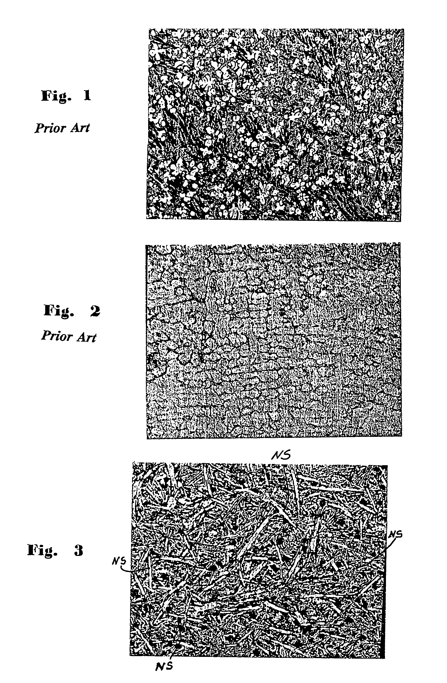
[0035]FIG. 1 is a photomicrograph at 200× magnification of a metallurgically polished prior art hardfacing deposit of commercially available ARMACOR (™) material.

[0036]FIG. 2 is a photomicrograph at 200× magnification of a polished prior art hardfacing deposit of commercially available ARNCO 200 XT (™) material. The deposit as shown in FIG. 2 has grains of non-uniform size and distinct carbide pieces are present that contribute to cracking. The prior art materials of FIG. 1 and FIG. 2 have a generally randomly sized grain structure, which is relatively uncontrolled. The different sizes of the particles in the material of FIG. 1 and FIG. 2 contribute to metallurgical notches (stress risers) that can promote cracking.

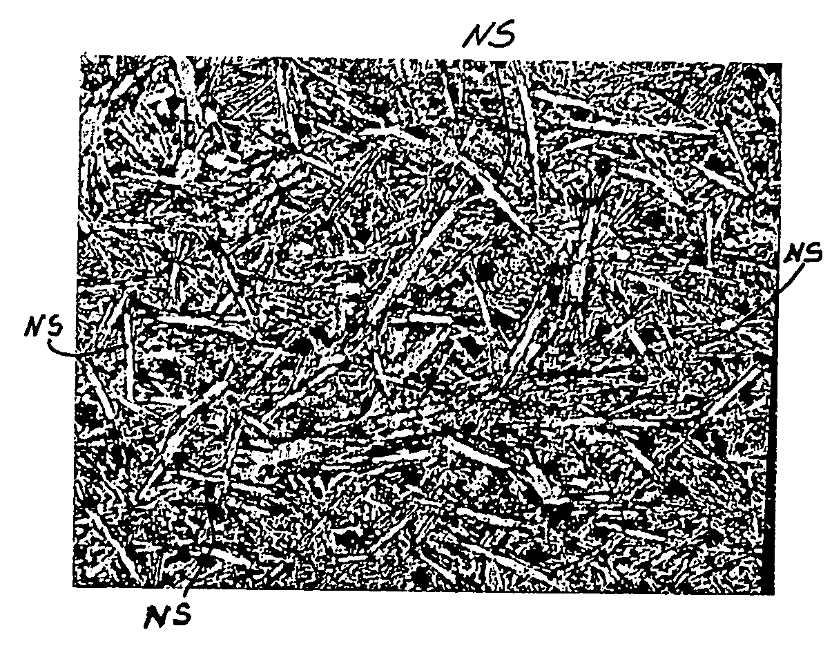
[0037]FIG. 3 is a photomicrograph at a 200× magnification of a welded cross-section of hardfacing material according to the present invention whose composition is as follows (each % by weight):

[0038]

Chromium29.10-30.00%Nickel5.00-6.00%Titanium1.00-2.10%Boron3.00-3.90%Sili...


PUM

PropertyMeasurementUnit
thicknessaaaaaaaaaa
thicknessaaaaaaaaaa
wear resistantaaaaaaaaaa

Abstract

An item made of wear resistant material, the item, in certain aspects, made by a method including forming a mass of wear resistant material, the wear resistant material comprising at least one element from the group consisting of arsenic, antimony, cerium and bismuth, wherein the at least one element is present by weight as between 0.01% to 0.0001% of a total weight of the wear resistant material, wherein the wear resistant material includes by weight percent chromium 29.10-30.00%; nickel 5.00-6.00%; titanium 1.00-2.10%; boron 3.00-3.90%; silicon 1.00-2.10%; manganese 1.10-2.00%; iron-balance.

Description

RELATED APPLICATION[0001]This is a continuation-in-part of U.S. application Ser. No. 10 / 286,307 now U.S. Pat. No. 6,888,088, filed Nov. 1, 2002 which is incorporated fully herein for all purposes and from which the present invention claims priority under the Patent Laws.BACKGROUND OF THE INVENTION[0002]1. Field of the Invention[0003]The present invention is directed to items made of wear resistant material, e.g., ingots: to hardfacing materials; and to methods for applying them.[0004]2. Description of Related Art[0005]Pieces, parts and components in a variety of machines, devices, and apparatuses are subjected to abrasive and erosive wear, often in a corrosive media. For years attempts have been made to solve these problems by applying hard wear resistant layers to these components, e.g. means as brazing inserts of hard materials to critical areas or by applying hard coatings to the surfaces by detonation gun, plasma arc spraying (transferred and non-transferred), welding (gas or el...

Claims


Application Information

Patent Timeline
Patent Type & Authority Patents(United States)
IPC IPC(8): C22C38/40C22C33/04C22C37/08B23K9/04B23K26/34C23C30/00
CPCB23K9/04B23K26/34C23C30/00B23K26/3266B23K26/345Y10T428/12472Y10T428/12014Y10T428/24917Y10T428/12951Y10T428/12396B23K26/342B23K26/32B23K2103/50
Inventor BOLTON, JIMMIE BROOKSROGERS, BILLI MARIE
Owner GUY L MCCLUNG III
Learn More