
Cylinder, plasma apparatus, gas laser apparatus, and method of manufacturing cylinder

a technology of plasma apparatus and cylinder, which is applied in the direction of gas laser construction details, electrical equipment, laser details, etc., can solve the problems of gas laser apparatus durability degradation, gas laser tube service life reduction, etc., and achieves short manufacturing time, high plasma resistance, and low cost

Active Publication Date: 2017-06-22
KYOCERA CORP
View PDF6 Cites 0 Cited by
  • Summary
  • Abstract
  • Description
  • Claims
  • Application Information

AI Technical Summary

Benefits of technology

The patent text explains that plasma can be generated inside a cylinder without causing fractures or cracks. This results in a cylinder that is resistant to plasma, and can be made quickly and inexpensively.

Problems solved by technology

Corrosion of the laser tube due to the plasma causes a service life of the gas laser tube to be decreased and thus causes durability of the gas laser apparatus to be deteriorated.

Method used


Image

  • Cylinder, plasma apparatus, gas laser apparatus, and method of manufacturing cylinder
  • Cylinder, plasma apparatus, gas laser apparatus, and method of manufacturing cylinder
  • Cylinder, plasma apparatus, gas laser apparatus, and method of manufacturing cylinder

Examples


Embodiment Construction

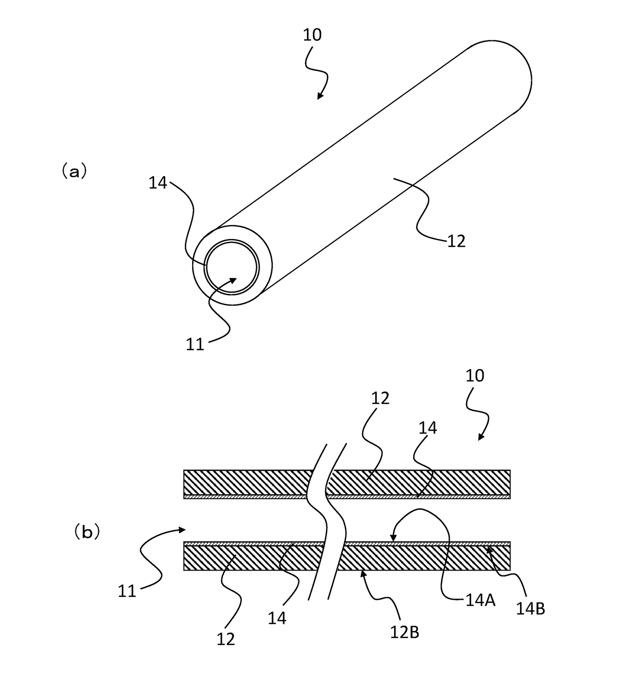
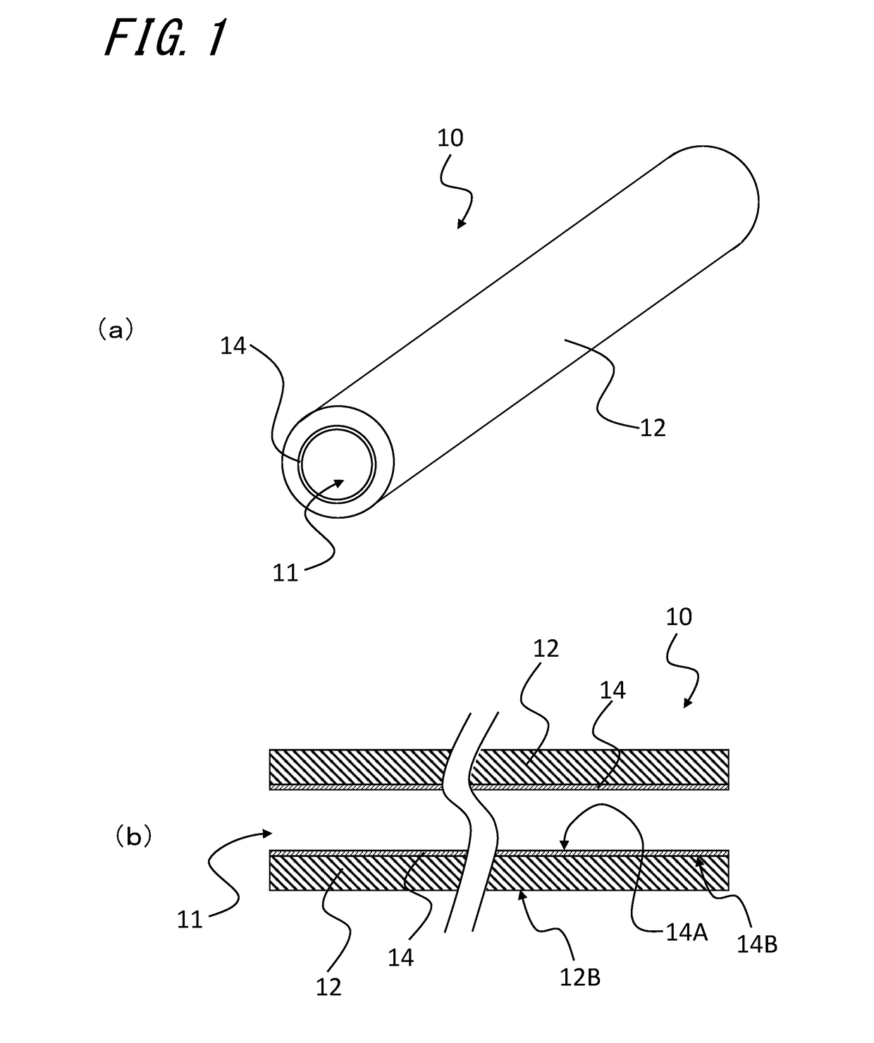
[0016]Now, embodiments of the invention will be described in detail with reference to the accompanying drawings. FIG. 1 is a view showing a laser tube 10 as one embodiment of a cylinder. FIG. 1(a) is a perspective view of the laser tube 10 and FIG. 1(b) is a sectional view.

[0017]The laser tube 10 includes a first cylinder 14 having an inner surface 14A exposed and a second cylinder 12 joined to an outer surface 14B of the first cylinder 14, the second cylinder 12 containing alumina as a main component, and the first cylinder 14 contains yttrium-containing oxide as a main component. For example, the first cylinder 14 contains as a main component yttria (Y2O3), which is yttrium-containing oxide. The phrase “contains as a main component” means that the content thereof is 50% by mass or more. The first cylinder 14 and the second cylinder 12 are preferably configured to contain the main components of 90% by mass or more. Contents of components constituting each member may be obtained by ...


PUM


Abstract

There is provided a cylinder including a first cylinder having an inner surface exposed; and a second cylinder joined to an outer surface of the first cylinder, the second cylinder containing alumina as a main component, the first cylinder containing yttrium-containing oxide as a main component.

Description

TECHNICAL FIELD[0001]The present invention relates to a cylinder, a plasma apparatus, a gas laser apparatus and a method of manufacturing the cylinder.BACKGROUND ART[0002]As apparatuses for oscillating laser to be used for cutting of materials or various measurements, for example, a gas laser apparatus for oscillating a gas laser is widely used. In the gas laser apparatus, a rare gas such as helium-neon (He—Ne) gas or argon (Ar) gas, and, for example, carbon dioxide gas (CO2 gas) or the like are enclosed in a conduit of a gas laser tube, which is a circular-shaped cylinder, and plasma is generated in the conduit. Then, by exciting, for example, carbon dioxide gas molecules (CO2 molecules) by energy of the plasma, light of a specific wavelength is emitted from the carbon dioxide gas molecules (CO2 molecules). For materials used for the gas laser tube, a high airtightness and also a high transparency to a high-frequency electric power for generating plasma are required, and thus for e...

Claims


Application Information

Patent Timeline
Patent Type & Authority Applications(United States)
IPC IPC(8): H01S3/032H01S3/03
CPCH01S3/0305H01S3/032
Inventor NOGUCHI, YUKIO
Owner KYOCERA CORP
Learn More