Eureka AIR delivers breakthrough ideas for toughest innovation challenges, trusted by R&D personnel around the world.

Fuel cell system

Active Publication Date: 2019-08-29
TOYOTA JIDOSHA KK
View PDF0 Cites 1 Cited by
  • Summary
  • Abstract
  • Description
  • Claims
  • Application Information

AI Technical Summary

Benefits of technology

The invention provides a fuel cell system with a guide rib on the inner wall of the fuel gas inlet communication hole of the stack manifold on the side opposite to the power generation portions of the fuel cell stack. This results in improved performance of the fuel cell system. Additionally, the invention also provides a method for measuring the amount of liquid water in the mixed gas. This method involves extracting liquid water with the highest percentage of impurities from each of the examples and measuring the quantity of liquid water extracted from each example.

Problems solved by technology

Further, if such impurities enter the fuel cell stack along with the fuel gas flow, the power generating capability of the fuel cells may be deteriorated.
However, in the aforementioned fuel cell system, since the flow generated with the incoming fuel off-gas in the fuel gas supply channel becomes spiral, impurities contained in the fuel off-gas may intensively collect near the inlets of the fuel cells.

Method used


Image

  • Fuel cell system
  • Fuel cell system
  • Fuel cell system

Examples


Embodiment Construction

[0016]An embodiment of the fuel cell system according to the present disclosure will be described below with reference to the drawings. The fuel cell system according to the present disclosure may be mounted on and used as a drive source for vehicles, vessels, aircrafts, trains, and the like, or used for a power generation facility of buildings.

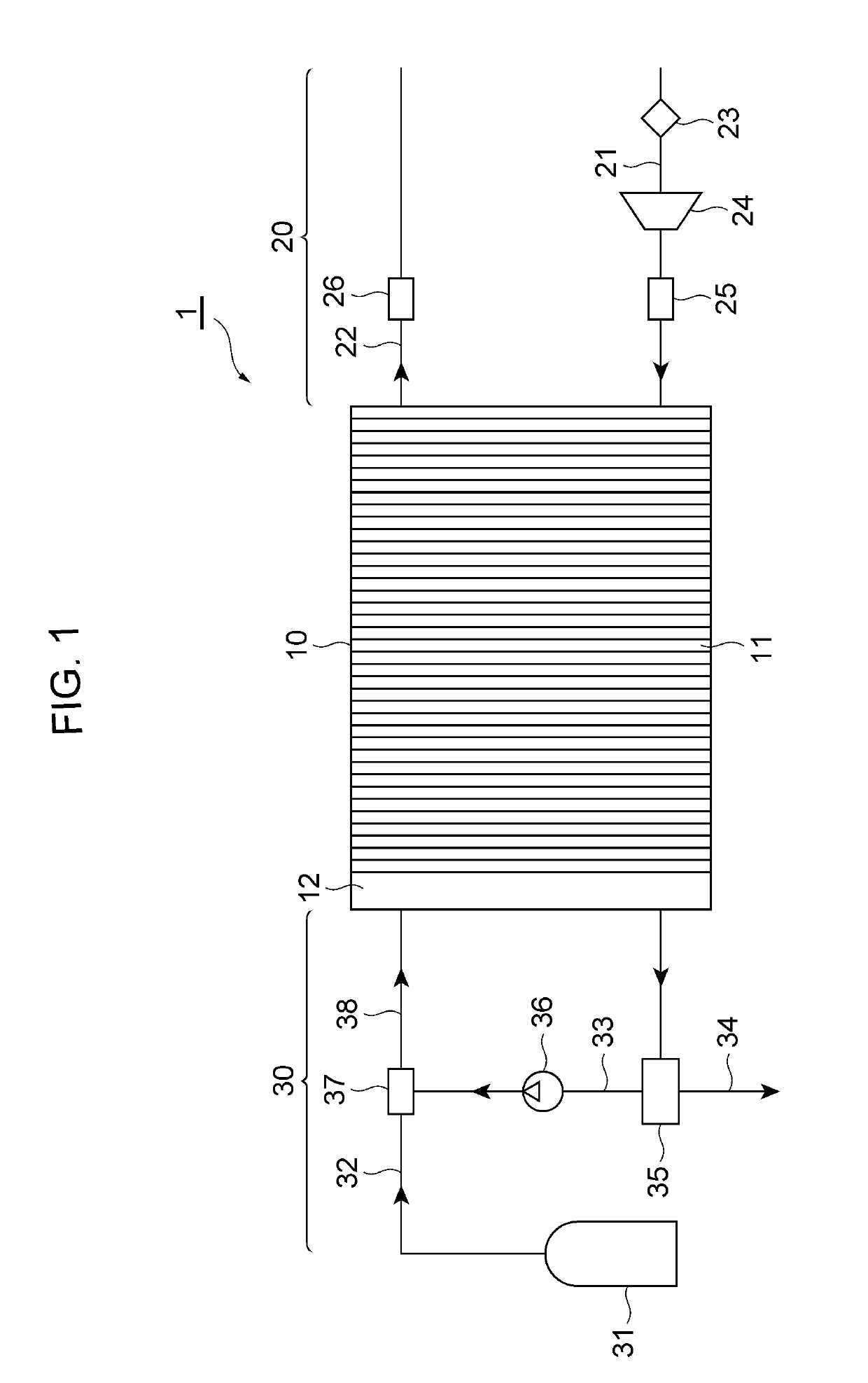
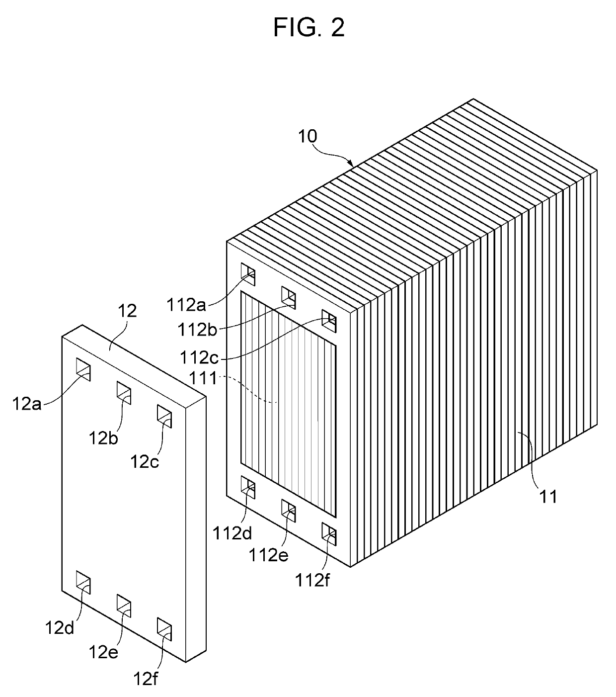
[0017]FIG. 1 is a schematic configuration diagram of a fuel cell system according to an embodiment, and FIG. 2 shows perspective views of a fuel cell stack and a stack manifold. A fuel cell system 1 of the present embodiment mainly includes a fuel cell stack 10, an oxidant gas supply system 20 that is adapted to supply an oxidant gas such as air to the fuel cell stack 10, and a fuel gas supply system 30 that is adapted to supply a fuel gas such as hydrogen to the fuel cell stack 10.

[0018]The fuel cell stack 10 is a cell stack formed by stacking a plurality of fuel cells 11 and is a polymer electrolyte fuel cell. Though not shown, each fuel ce...


PUM


Abstract

A fuel cell system that can prevent impurities from intensively collecting near inlets of fuel cells. The fuel cell system includes a fuel cell stack formed by stacking fuel cells, each fuel cell having a power generation portion, a stack manifold with a fuel gas inlet communication hole disposed at an end of the fuel cell stack in the stacking direction of the fuel cells, a mixed gas supply channel communicating with the fuel gas inlet communication hole for supplying a mixed gas of a fuel gas and fuel off-gas to the fuel cell stack, a stirring mixer for swirling the mixed gas provided in the mixed gas supply channel, and a guide rib provided on the inner wall of the fuel gas inlet communication hole of the stack manifold, on the side opposite to the side of the power generation portions of the fuel cells.

Description

CROSS REFERENCE TO RELATED APPLICATIONS[0001]The present application claims priority from Japanese patent application JP 2018-030325 filed on Feb. 23, 2018, the content of which is hereby incorporated by reference into this application.BACKGROUNDTechnical Field[0002]The present disclosure relates to a fuel cell system.Background Art[0003]As a conventional technique in this field, there has been known a fuel cell system that includes a fuel cell stack formed by stacking a plurality of fuel cells, a fuel gas supply channel that is adapted to supply a fuel gas such as hydrogen to the fuel cell stack, and a circulation channel that is adapted to reflux a fuel off-gas (that is, an unconsumed fuel gas) that has been discharged from the fuel cell stack to the fuel gas supply channel. In the fuel cell system with such a configuration, the fuel off-gas flowing through the circulation channel may possibly contain produced water that has not been fully separated from the off-gas by a gas-liqui...

Claims


Application Information

Patent Timeline
IPC IPC(8): H01M8/2483H01M8/2457H01M8/241H01M8/04119
CPCH01M8/2457H01M8/2483H01M8/04149H01M8/241H01M8/2484H01M8/24H01M8/0662H01M8/04097H01M8/04201H01M8/04156H01M2250/20Y02T90/40Y02E60/50
Inventor KURITA, SHUJISUZUKI, YUSHI
Owner TOYOTA JIDOSHA KK
Why Eureka
Eureka Blog
Learn More