Overvoltage protection circuit and electrical device including such a protection circuit

a protection circuit and voltage withstand technology, applied in the field of overvoltage protection circuits, can solve the problems of limited lifespan, device disturbance, and transistor voltage withstand strength less than 2 kv, and achieve the effect of easy adaptation

Active Publication Date: 2019-09-05
SCHNEIDER ELECTRIC IND SAS
View PDF0 Cites 1 Cited by
  • Summary
  • Abstract
  • Description
  • Claims
  • Application Information

AI Technical Summary

Benefits of technology

[0007]The aim of the invention is a protection circuit avoiding the drawbacks of the devices of th

Problems solved by technology

Such devices are then subject to disturbances, transmitted by the electrical network.
Components of varistor type are often used to dissipate the energy of the overvoltages with the drawback of a limited lifespan, all the shorter when the number and the energy of the disturbances is high.
Currently, the transistors have a voltage withstand strength lower than 2 kV which is inadequate for withstanding overvoltages of an amplitude lying between 6 and 8 kV, conventionally measured in the event of lightning strikes.
However, the protection circuit requires fast bipolar transistors to discharge the stray capacitances between gate and source of the MOSFET transistors an

Method used


Image

  • Overvoltage protection circuit and electrical device including such a protection circuit
  • Overvoltage protection circuit and electrical device including such a protection circuit
  • Overvoltage protection circuit and electrical device including such a protection circuit

Examples


Embodiment Construction

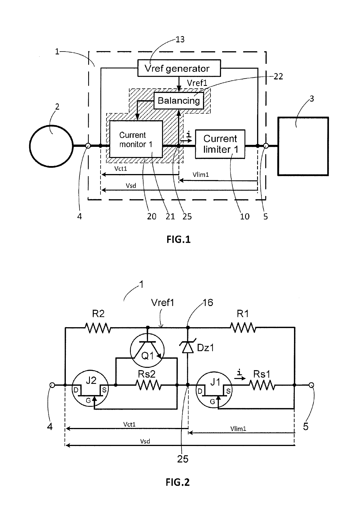
[0046]FIG. 1 is a block diagram to illustrate a principle of operation of a protection circuit 1 according to the invention. Such a protection circuit 1 comprises an input 4 intended to be connected to an electrical energy source 2. The electrical energy source 2 is also a source of electrical disturbances such as overvoltages and lightning waves. The protection circuit 1 comprises an output 5 intended to be connected to an electrical load 3 to be protected from the electrical disturbances emitted by the energy source 2. A current i circulates between the electrical energy source 2 and the electrical load 3 in order to supply the electrical load with electrical energy. The current i passes through the protection device 1.

[0047]The protection circuit 1 comprises a current limiting circuit 10 connected, on one side, to the output 5, and, on the other side, to a first current monitoring circuit 21. The first current monitoring circuit 21 is connected to the input 4. The current limitin...


PUM


Abstract

A protection circuit intended to be connected between an electrical energy source and an overvoltage-sensitive device. A current limiting circuit and a current monitoring circuit are connected in series, a reference voltage generator circuit delivering a reference voltage, and a balancing circuit is intended to control the current monitoring circuit so that the voltage at a point of connection between the current limiting circuit and the current monitoring circuit is substantially equal to the reference voltage. An electrical measurement or power supply device including at least one such overvoltage protection circuit.

Description

TECHNICAL FIELD[0001]The present invention relates to an overvoltage protection circuit comprising an input intended to be connected to an electrical energy source and an output intended to be connected to a device to be protected against overvoltages. The invention relates also to an electrical measurement or power supply device comprising at least one such overvoltage protection circuit.STATE OF THE ART[0002]Many electrical devices are connected to the electrical network for their energy supply. Such devices are then subject to disturbances, transmitted by the electrical network. Among the disturbances, there are the overvoltages that can be of natural origin, such as a lightning strike, or generated by the operation of an electrical device such as the control of an inductive load, for example a motor. The overvoltages transmitted over the electrical network can be of very high energy, so the electrical devices must be protected to avoid the degradation thereof. This protection re...

Claims


Application Information

Patent Timeline
IPC IPC(8): H02H9/04H02H1/00
CPCH02H1/0007H02H9/04H02H9/02H02H9/025
Inventor LI, BOWANG, MIAO-XIN
Owner SCHNEIDER ELECTRIC IND SAS
Why Eureka
Try Eureka