
Block management method, memory control circuit unit and memory storage apparatus

a memory control circuit and block management technology, applied in the direction of memory adressing/allocation/relocation, instruments, fault response, etc., can solve the problems of limited physical block erase count, over-wearing of certain physical blocks, and significant reduction of the lifetime of flash memory storage apparatuses

Active Publication Date: 2019-09-12
PHISON ELECTRONICS
View PDF21 Cites 4 Cited by
  • Summary
  • Abstract
  • Description
  • Claims
  • Application Information

AI Technical Summary

Benefits of technology

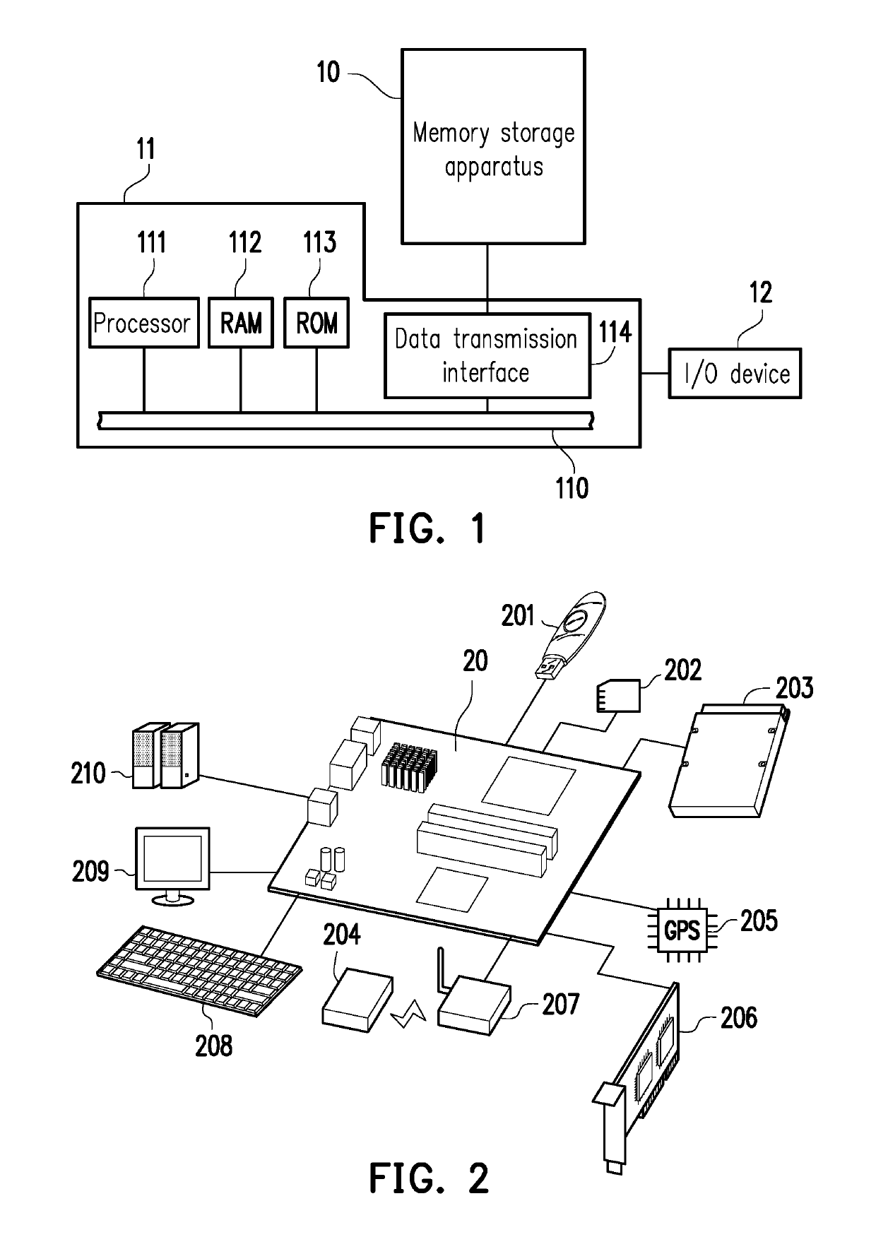
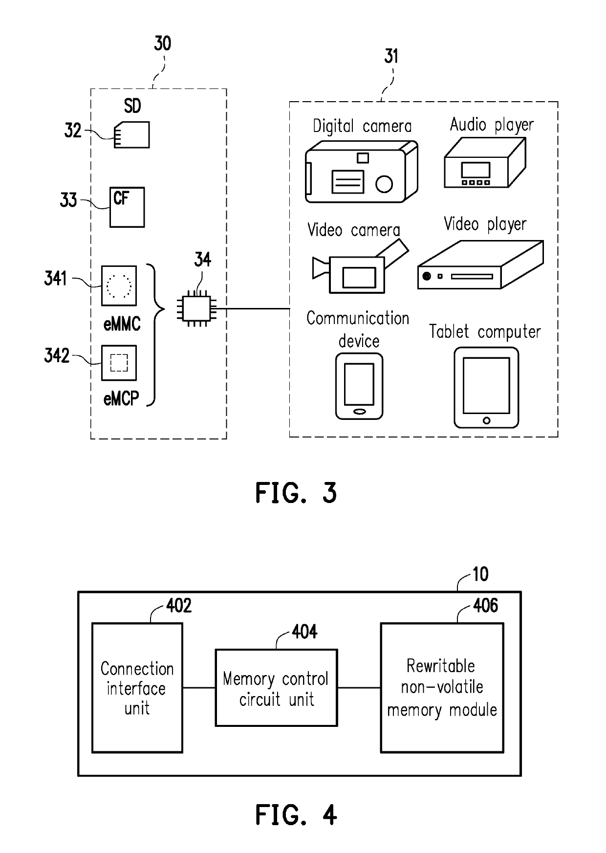
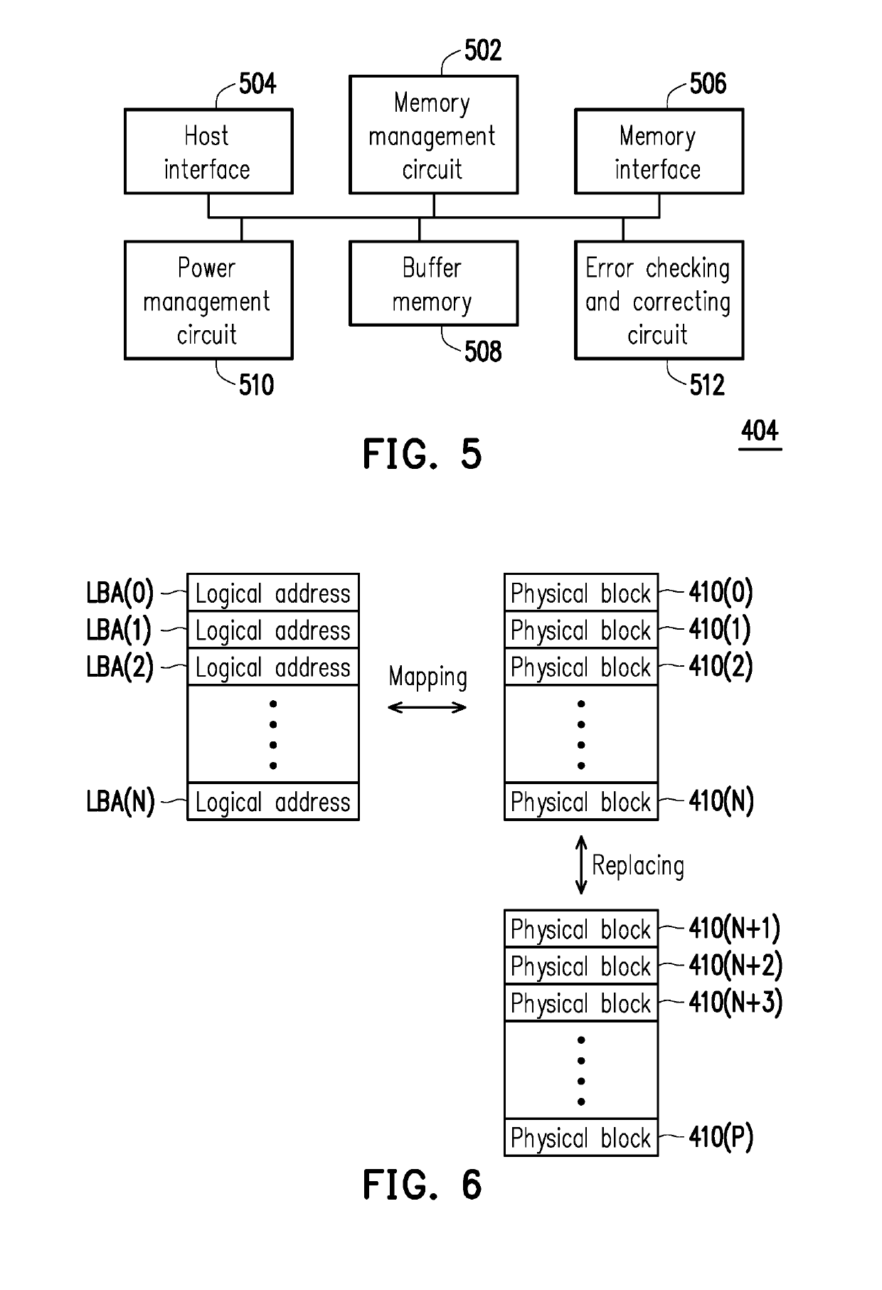
The present invention is about a method for managing data in a memory system, specifically a memory control circuit unit and a memory storage apparatus. The method uses a block recognition machine learning model to identify parameters of physical blocks in the memory system and group them into different groups based on those parameters. This helps to evenly use all of the physical blocks in the memory system. The memory control circuit unit includes a host interface, a memory interface, and a memory management circuit that works together to manage data in the memory system. The technical effects of this invention include improving memory system performance and efficiency by optimizing data management and usage.

Problems solved by technology

However, an erase count of the physical block is limited (e.g., the physical block will be damaged after being erased over 10,000 times), and thus the lifetime of the flash memory storage apparatus will be significantly reduced if the physical blocks are frequently erased.
For example, wearing levels of certain physical blocks may be overly high while the wearing levels of some other physical blocks are overly low.

Method used


Image

  • Block management method, memory control circuit unit and memory storage apparatus
  • Block management method, memory control circuit unit and memory storage apparatus
  • Block management method, memory control circuit unit and memory storage apparatus

Examples


Embodiment Construction

[0027]Reference will now be made in detail to the present preferred embodiments of the invention, examples of which are illustrated in the accompanying drawings. Wherever possible, the same reference numbers are used in the drawings and the description to refer to the same or like parts.

[0028]Embodiments of the present invention may comprise any one or more of the novel features described herein, including in the Detailed Description, and / or shown in the drawings. As used herein, “at least one”, “one or more”, and “and / or” are open-ended expressions that are both conjunctive and disjunctive in operation. For example, each of the expressions “at least one of A, B and C”, “at least one of A, B, or C”, “one or more of A, B, and C”, “one or more of A, B, or C” and “A, B, and / or C” means A alone, B alone, C alone, A and B together, A and C together, B and C together, or A, B and C together.

[0029]It is to be noted that the term “a” or “an” entity refers to one or more of that entity. As s...


PUM


Abstract

A block management method, a memory control circuit unit and a memory storage apparatus for managing a plurality of physical blocks are provided. The method includes reading user data from a first physical block among physical blocks to obtain a plurality of parameters; inputting the parameters corresponding to the first physical block into a machine learning based block recognizer to group the first physical block into a first block group or a second block group according to an output result of the machine learning based block recognizer; establishing a first and second block mapping tables; mapping logical addresses of the first and second block mapping tables to the physical blocks belonging to the first and second block groups. The parameters may comprise at least one of a read busy time parameter, an error bit position parameter and a storage retention parameter. A machine learning operation may be performed using first and second test physical blocks, and corresponding parameters, as training data. A usage status may be determined according to the parameters, and blocks with a usage status of good may be used first to evenly use all the physical blocks.

Description

CROSS-REFERENCE TO RELATED APPLICATION[0001]This application claims the priority benefit of Taiwan application serial no. 107107330, filed on Mar. 6, 2018. The entirety of the above-mentioned patent application is hereby incorporated by reference herein and made a part of this specification.BACKGROUNDTechnical Field[0002]The invention relates to a block management method, a memory control circuit unit and a memory storage apparatus, and more particularly, relates to a block management method based on machine learning, a memory control circuit unit and a memory storage apparatus using the method.Description of Related Art[0003]The markets of digital cameras, cellular phones, and MP3 players have expanded rapidly in recent years, resulting in escalated demand for storage media by consumers. The characteristics of data non-volatility, low power consumption, compact size and non-mechanical structure make a rewritable non-volatile memory module (e.g., a flash memory) ideal to be built in...

Claims


Application Information

Patent Timeline
Patent Type & Authority Applications(United States)
IPC IPC(8): G06F3/06G06F12/02G06F11/10G11C29/52G06F15/18
CPCG06F3/0659G06N20/00G06F12/0246G06F3/064G06F2212/7201G06F11/1044G06F11/106G06F3/0679G11C29/52G11C29/028G11C29/44G11C8/06G11C29/42G11C2029/0411G06F11/1048G06F3/0616G06F2212/7211G06F2212/502
Inventor LAM, SIU-TUNGLEE, MING-YENLEE, KUO-LUNG
Owner PHISON ELECTRONICS
Learn More