Wireless communication device

a communication device and wireless technology, applied in semiconductor devices, semiconductor/solid-state device details, instruments, etc., can solve the problem that the entire surface on the front surface side of the dielectric substrate is not efficiently used in this configuration, and achieve excellent communication characteristics and high efficiency. the effect of a high-efficiency antenna

Active Publication Date: 2019-09-12
MURATA MFG CO LTD
View PDF0 Cites 3 Cited by
  • Summary
  • Abstract
  • Description
  • Claims
  • Application Information

AI Technical Summary

Benefits of technology

[0010]The exemplary embodiments of the present invention provide the wireless communication device configured for enabling a metal surface of an article to highly efficiently function as an antenna while the wireless communication device is attached to the metal surface of the article and thereby performing wireless communication with excellent communication characteristics, as compared to a conventional wireless communication device.

Problems solved by technology

In such a wireless communication device, the formation position of the second electrode must be ensured at a position separated from the first electrode on the front surface side of the dielectric substrate, so that the entire surface on the front surface side of the dielectric substrate is not efficiently used in this configuration.

Method used


Image

  • Wireless communication device
  • Wireless communication device
  • Wireless communication device

Examples


first exemplary embodiment

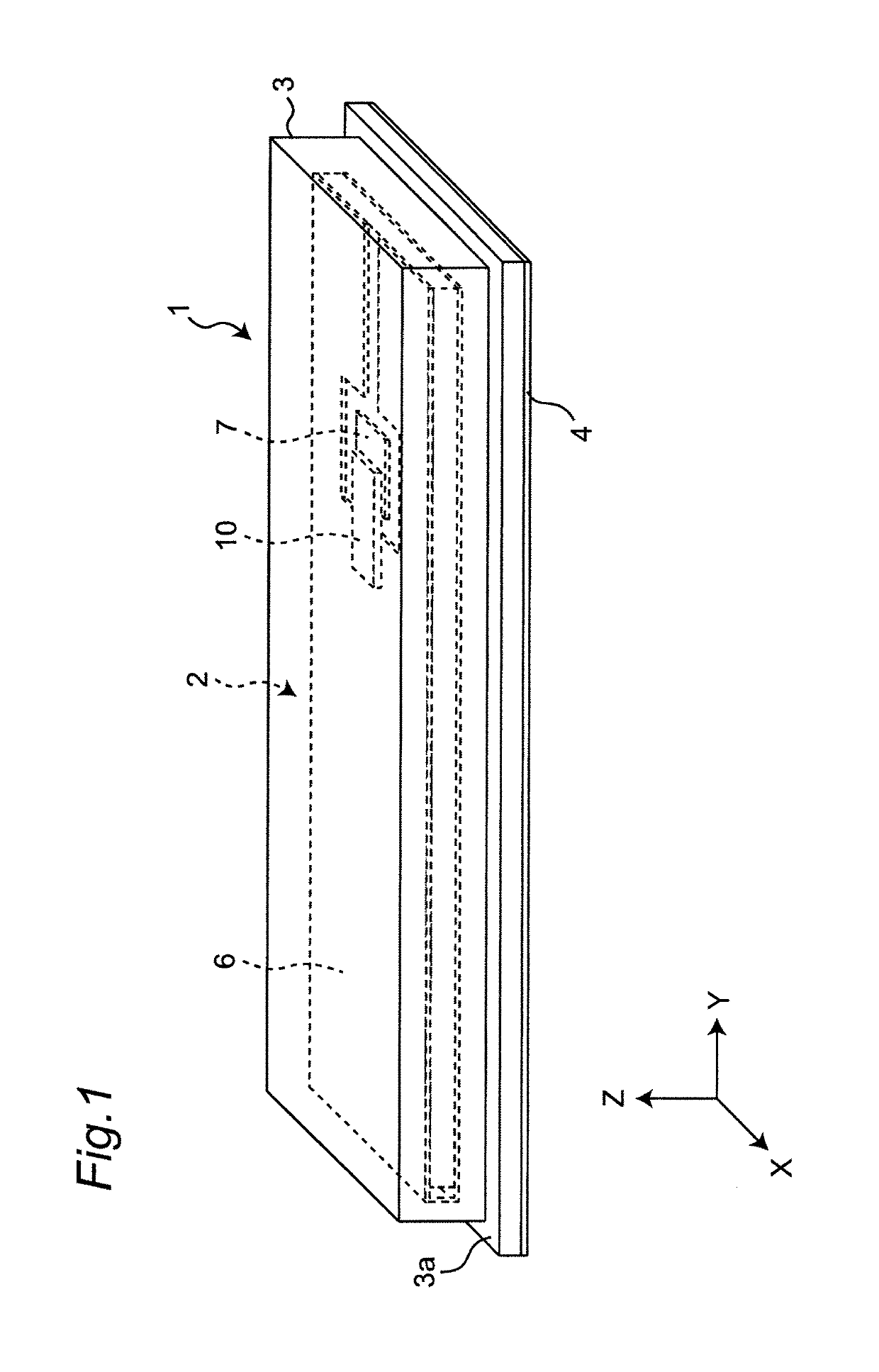
[0046]FIG. 1 is a perspective view showing a wireless communication device 1 according to a first exemplary embodiment. To facilitate understanding of the exemplary embodiments of the invention, it is noted that the drawings show an X-Y-Z coordinate system including X, Y and Z axes orthogonal to each other. In this description, Z-, X-, and Y-axis directions are defined as a thickness direction, a width direction (lateral direction), and a length direction (longitudinal direction), respectively, of the wireless communication device having a rectangular shape, although it should be appreciated that these axes may change depending on the orientation of the device 1.

[0047]As shown, the wireless communication device 1 of in FIG. 1 is an RFID tag configured to perform wireless communication at a carrier frequency of the UHF band, for example, 900 MHz, and is configured to be attached to various articles before use and, particularly, the device is configured for wireless communication even...

second embodiment

[0088]The wireless communication device 1 (RFID tag) of the second exemplary embodiment will hereinafter be described. The wireless communication device 1 of the second embodiment is also configured to perform wireless communication through a high frequency signal having a UHF-band communication frequency (carrier frequency) and is configured to enable wireless communication in a wide frequency band. The wireless communication device 1 of the second embodiment is different from the configuration of the first embodiment described above in configuration of a first electrode 6A and a second electrode 7A in a wireless communication module 2A, and the other configurations are the same as the configuration of the wireless communication module 2 in the first embodiment. Therefore, in the description of the wireless communication device 1 of the second embodiment, the first electrode 6A and the second electrode 7A of the wireless communication module 2A in the second embodiment will mainly ...

third embodiment

[0094]The wireless communication device 1 (RFID tag) of a third exemplary embodiment will hereinafter be described. The wireless communication device 1 of the third embodiment is also configured to perform wireless communication through a high frequency signal having a UHF-band communication frequency (carrier frequency) and is configured to enable wireless communication in a wide frequency band. The wireless communication device 1 of the third embodiment is different from the wireless communication device 1 of the first embodiment described above in configuration of a first electrode 6B and a second electrode 7B in a wireless communication module 2B, and the other configurations are the same as the wireless communication module 2 in the first embodiment. Therefore, in the description of the wireless communication device 1 of the third embodiment, the first electrode 6B and the second electrode 7B of the wireless communication module 2B will mainly be described. In the description o...


PUM


Abstract

A wireless communication device that includes a first electrode connected to a first terminal electrode of an RFIC element and a second electrode connected to a second terminal electrode of the RFIC element. Moreover, the first electrode has a longitudinal direction and a lateral direction and has a first portion connected to the first terminal electrode and a second portion that faces the first portion and the second electrode. The first portion has an extended portion that extends in the longitudinal direction beyond a connection point between the second electrode and the second terminal electrode.

Description

CROSS REFERENCE TO RELATED APPLICATIONS[0001]The present application is a continuation of PCT / JP2018 / 036232 filed Sep. 28, 2018, which claims priority to Japanese Patent Application No. 2017-191521, filed Sep. 29, 2017, the entire contents of each of which are incorporated herein by reference.TECHNICAL FIELD[0002]The present invention relates to a wireless communication device using an RFID (Radio Frequency Identification) technique and, more particularly, to a wireless communication device attached to a metal surface of an article to perform wireless communication.BACKGROUND[0003]A conventional wireless communication device capable of being attached to a metal surface of an article and performing wireless communication are described in Patent Document 1 (identified below), for example. The wireless communication device described in Patent Document 1 is formed by disposing a first electrode and a second electrode on a front surface of a thin plate-shaped dielectric substrate and con...

Claims


Application Information

Patent Timeline
Patent Type & Authority Applications(United States)
IPC IPC(8): H01Q1/22H01L23/498H01L23/31H01L23/544H01L23/66H01L23/14G06K19/07G06K19/077
CPCH01L23/49855H01L23/4985H01L2223/6616G06K19/0775H01L2223/6677H01L23/544H01Q1/22H01L23/145G06K19/0723H01L23/552H01L23/66H01L23/3121G06K19/0779G06K19/07786H01L2224/16225H01L23/053H01Q1/24G06K19/077
Inventor KATO, NOBORU
Owner MURATA MFG CO LTD
Why Eureka
Try Eureka