Clutch device

a technology of clumping and rotor, which is applied in the direction of clumping, friction clutches, actuators, etc., can solve the problems of insufficient stiffness of the pressure plate, and achieve the effect of enhancing the stiffness of the rotor including a plurality of cam protrusions and/or plurality of openings

Active Publication Date: 2019-09-19
EXEDY CORP
View PDF8 Cites 1 Cited by
  • Summary
  • Abstract
  • Description
  • Claims
  • Application Information

AI Technical Summary

Benefits of technology

[0027]Overall, in the present advancement described above, the strength of a rotor in

Problems solved by technology

Hence, the openings result in insuffici

Method used


Image

  • Clutch device
  • Clutch device
  • Clutch device

Examples


Embodiment Construction

[Entire Configuration]

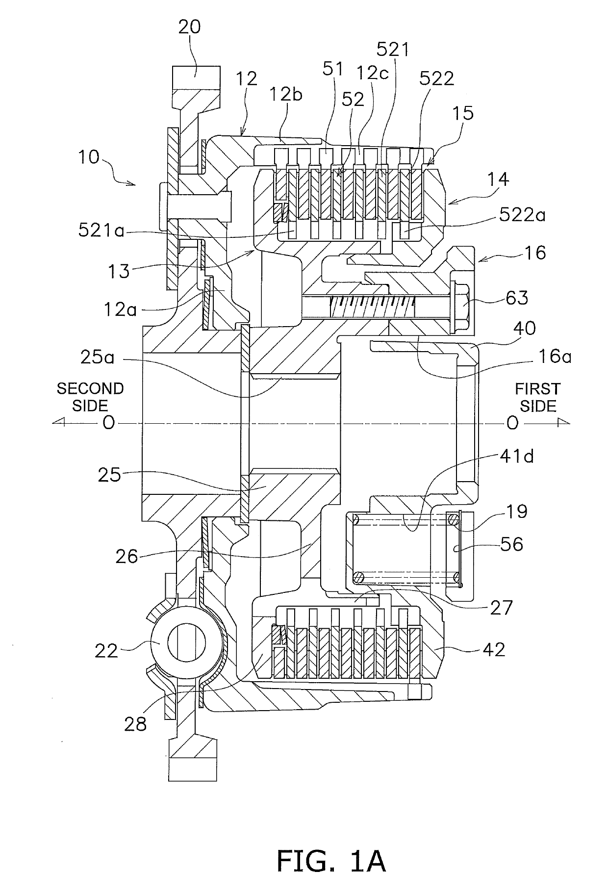
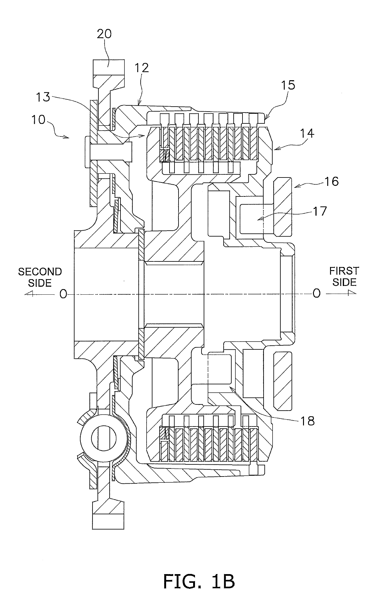
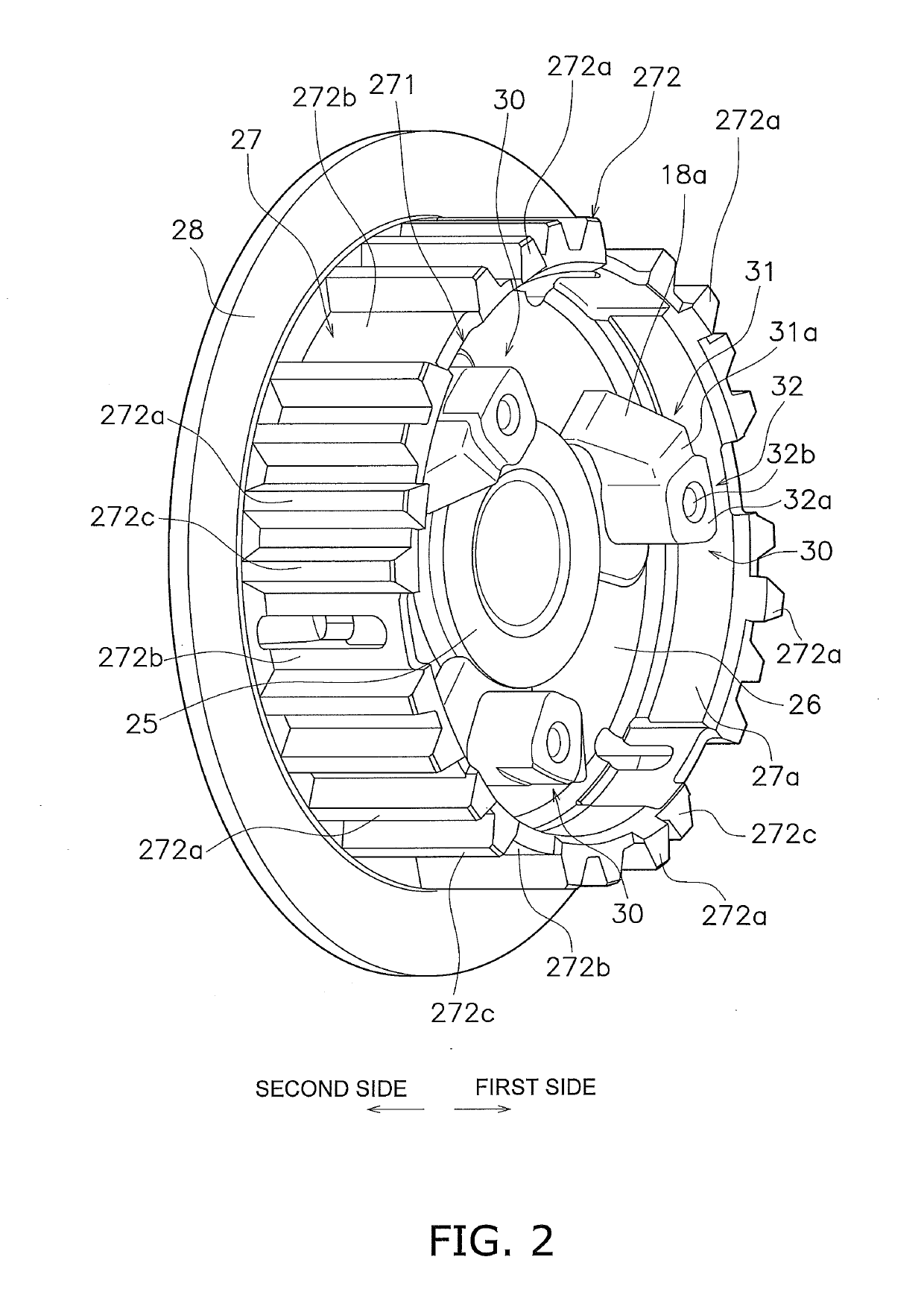
[0041]FIGS. 1A to 8 show a clutch device 10 for a motorcycle as a clutch device according to a preferred embodiment of the present disclosure. FIG. 1A is a cross-sectional view of the clutch device 10, whereas FIG. 1B is a cross-sectional view of the clutch device 10 taken at a different position from FIG. 1A. On the other hand, FIGS. 2 to 4 and 7 are external perspective views of major members. In the cross-sectional views of FIGS. 1A and 1B, line O-O indicates a rotational axis. It should be noted that in the following explanation, the term “axial direction” indicates an extending direction of the rotational axis O. As shown in FIGS. 1A and 1B, the right side in FIGS. 1A and 1B is defined as “a first side in the axial direction” whereas the left side in FIGS. 1A and 1B is defined as “a second side in the axial direction”.

[0042]The clutch device 10 is configured to allow or block transmitting power from an engine to a transmission. The clutch device 10 include...


PUM


Abstract

The disclosed clutch device includes a clutch housing, a clutch center, a pressure plate, a clutch part, and a cam mechanism. The clutch center includes a first tubular portion shaped to protrude to a first side in an axial direction. The pressure plate includes a plurality of cam portions and a second tubular portion. The plurality of cam portions include a plurality of cam surfaces shaped to protrude to a second side in the axial direction. The second tubular portion is provided on an inner peripheral side of the first tubular portion so as to protrude to the second side in the axial direction. The second tubular portion couples at least part of the plurality of cam portions. The clutch part allows and blocks transmission of power from the clutch housing to an output side. The cam mechanism includes the plurality of cam surfaces and controls a pressing force applied to the clutch part.

Description

CROSS-REFERENCE TO RELATED APPLICATIONS[0001]This application claims priority to Japanese Patent Application No. 2018-046126, filed Mar. 14, 2018. The contents of that application are incorporated by reference herein in their entirety.BACKGROUND1. Technical Field[0002]The present disclosure relates to a clutch device.2. Description of the Related Art[0003]In general, motorcycles (a two-wheeled motorcycle, a buggy, etc.) use a clutch device so as to allow or block transmitting power from an engine to a transmission. The clutch device includes a clutch housing, a clutch center, a clutch part and a pressure plate. The clutch housing is coupled to an engine crankshaft side. The clutch center is coupled to a transmission side. The clutch part is disposed between the clutch housing and the clutch center so as to allow or block transmission of power. The pressure plate is provided for pressing the clutch part.[0004]A clutch device described in Japan Laid-open Patent Application Publication...

Claims


Application Information

Patent Timeline
IPC IPC(8): F16D13/56F16D23/12F16D23/06
CPCF16D23/06F16D2023/123F16D13/56F16D2121/005F16D23/12F16D13/52F16D2013/565
Inventor IMANISHI, YOSHIOKITAZAWA, HIDENORI
Owner EXEDY CORP
Why Eureka
Try Eureka