Proximity sensor, proximity illumination intensity sensor, electronic device, and proximity sensor calibration method
- Summary
- Abstract
- Description
- Claims
- Application Information
AI Technical Summary
Benefits of technology
Problems solved by technology
Method used
Image

Examples
embodiment 1
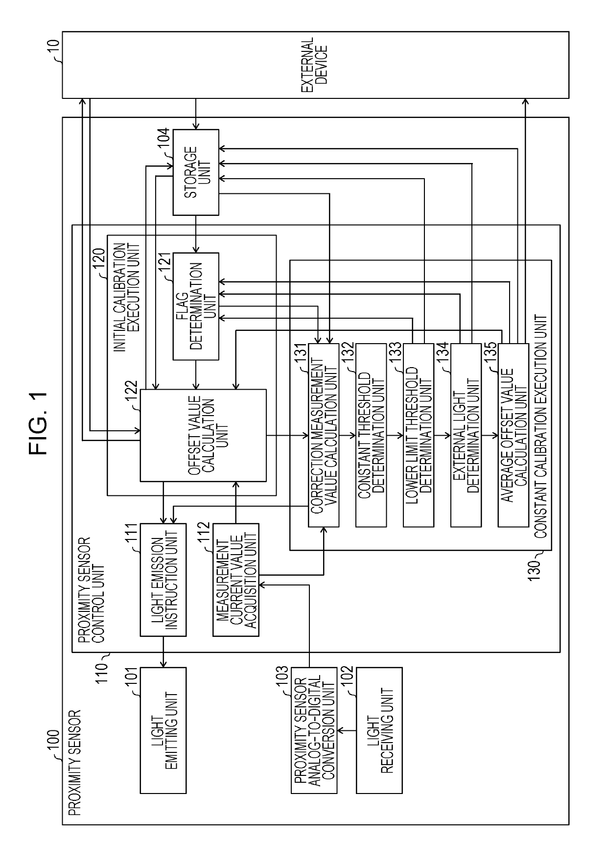
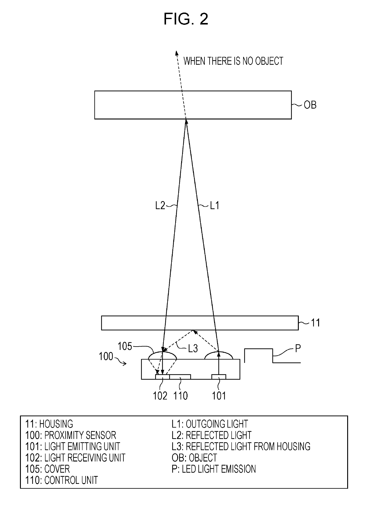
[0039]Embodiment 1 of the invention is described with reference to FIGS. 1 to 4. FIG. 1 is a functional block diagram illustrating a schematic configuration of a proximity sensor 100 according to Embodiment 1 of the invention. FIG. 2 is a view for explaining an operation principle of the proximity sensor 100. Note that, LED light emission P of FIG. 2 indicates a pulse signal for causing a light emitting unit 101 to emit light.
(Configuration of Proximity Sensor)
[0040]The proximity sensor 100 includes the light emitting unit 101, a light receiving unit 102, a proximity sensor analog-to-digital conversion unit 103, a storage unit 104, a cover 105, and a proximity sensor control unit 110, as illustrated in FIGS. 1 and 2.
[0041]The light emitting unit 101 emits light. Specifically, the light emitting unit 101 receives current supplied from a light emission instruction unit 111 described below and emits light. As the light emitting unit 101, for example, an infrared LED that emits infrared...
embodiment 2
[0119]The proximity illumination intensity sensor 400 of the embodiment of the invention is described as follows with reference to FIG. 5. Note that, for convenience of description, a member having the same function as that of the member described in Embodiment 1 is given the same reference sign and description thereof is omitted. FIG. 5 is a functional block diagram illustrating a schematic configuration of the proximity illumination intensity sensor 400 according to Embodiment 2 of the invention. The proximity illumination intensity sensor 400 includes the illumination intensity sensor function of detecting illumination intensity of external environment light in the proximity sensor 100.
[0120]The proximity illumination intensity sensor 400 illustrated in FIG. 5 has both the proximity sensor function of detecting whether or not a detection object is in proximity and the illumination intensity sensor function of measuring illumination intensity of external environment light, and is ...
embodiment 3
[0132]Embodiment 3 of the invention is described as follows with reference to FIGS. 6 and 7. Note that, for convenience of description, a member having the same function as the member described in the foregoing embodiments is given the same reference sign and description thereof is omitted.
(Application of Proximity Sensor)
[0133]An exemplary application of the proximity sensor 100 is described. First, as an example, a case where a mobile phone or a media player is used as an electronic device is described.
[0134]When there is an incoming call to the mobile phone, a user performs an action to put the mobile phone on his or her ear. At this time, in a case where display of a screen with a touch panel is on and a touch panel function is in an active state, when the user puts the mobile phone on his or her ear and human skin contacts with the screen, the mobile phone may be erroneously operated. In order to prevent such an erroneous operation, the proximity sensor 100 is used.
[0135]Specif...
PUM
 Abstract
Description
Claims
Application Information
 - R&D
- Intellectual Property
- Life Sciences
- Materials
- Tech Scout
- Unparalleled Data Quality
- Higher Quality Content
- 60% Fewer Hallucinations
Browse by: Latest US Patents, China's latest patents, Technical Efficacy Thesaurus, Application Domain, Technology Topic, Popular Technical Reports.
© 2025 PatSnap. All rights reserved.Legal|Privacy policy|Modern Slavery Act Transparency Statement|Sitemap|About US| Contact US: help@patsnap.com