Fault ride-through system

Inactive Publication Date: 2019-09-19
ROLLS ROYCE PLC +2
View PDF0 Cites 4 Cited by
  • Summary
  • Abstract
  • Description
  • Claims
  • Application Information

AI Technical Summary

Benefits of technology

The technology described in this patent provides a fault ride-through system with a dynamic power dissipater that helps to eliminate high voltage variation and harmonics during a fault condition. This improves the reliability and reduces the cost of the system. The controller can regulate the speed of the prime mover by controlling the power dissipation, which also reduces the current rating requirement of the solid state switch. The fault ride-through system only activates for severe grid faults that can cause rotor angle stability issues, resulting in a longer life time of the system. The power system may also further include a transformer to further reduce the current rating requirement of the solid state switch.

Problems solved by technology

Periods of lower electric network voltage are typically caused by faults on the far side of a unit transformer in the grid.
When a severe fault occurs in the power grid, the energy transmission to the system will be interrupted or reduced momentarily.
However, the mechanical power supplied to the generator is almost constant during the fault period due to the slower response in the mechanical system.
The unbalanced power in the generator set causes an acceleration of the generator rotor by the prime mover.
This acceleration may cause the angle between the generator rotor and the grid to increase, thereby causing the generator to run out of synchronism with the grid.
This is known as the rotor angle stability problem or pole slip.
Further, a large angle between the generator rotor and the grid generator may cause the generator to be subjected to extremely high currents (a current spike), which may cause the generator to be damaged and disconnected from the grid.
While the generator set itself typically has an internal speed governor which provides some internal capability to reduce acceleration of the rotor during a fault condition, the governor often does not sufficiently reduce the acceleration of the rotor to prevent the generator set from becoming out of synch with the grid by the time the system recovers to pre fault voltage levels.

Method used


Image

  • Fault ride-through system
  • Fault ride-through system
  • Fault ride-through system

Examples


Embodiment Construction

[0028]In the drawings, like reference numerals will be repeated for like features.

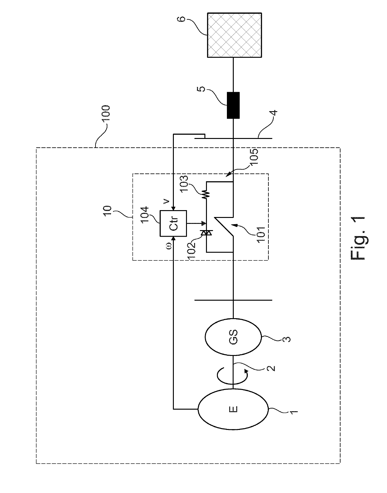
[0029]Wth reference to FIG. 1, there is provided a power system 100 for supplying electrical power to a power grid 6. The power system is connected to transmission lines 5 of the power grid 6 at a point of common coupling (PCC) 4, although in other arrangements the power system may be connected to distribution lines of the power grid at a point of common coupling (PCC).

[0030]The power system 100 includes a reciprocating engine 1 which drives a synchronous electrical generator 3. In particular, the engine 1 comprises a prime mover 2 which is configured to drive a rotor of the generator 3 relative to its stator windings to generate electrical energy. The engine 1 may be a gas turbine engine.

[0031]As can be seen in FIG. 1, the generator 3 is connected to the PCC 4 via a fault ride-through system 10 which is operable to limit the prime mover and rotor speed during a fault condition by effectively increasin...


PUM


Abstract

There is disclosed a fault ride-through system for use in a power system comprising a synchronous generator driven by a prime mover. The fault ride-through system comprises a mechanical switch connected in parallel with a dynamic power dissipater, wherein the dynamic power dissipater comprises a solid-state switch connected in series with a braking resistor. A controller is configured to control the mechanical switch and the solid-state switch to control the current through the braking resistor, based on received data indicative of one or more operation parameters of the power system.

Description

CROSS-REFERENCE TO RELATED APPLICATIONS[0001]This specification is based upon and claims the benefit of priority from UK Patent Application Number 1803977.6 filed on 13th Mar. 2019, the entire contents of which are incorporated herein by reference.TECHNICAL FIELD[0002]The present disclosure relates generally to a fault ride-through system, particularly the enhancement of fault ride-through capability for generator sets in parallel operation with power grids.BACKGROUND[0003]Generator sets, which typically comprise a unit transformer and a synchronous generator driven by a prime mover (of, e.g., an engine or turbine), are typically required to comply with strict requirements for connection to the power grid. These requirements are typically defined by a grid code issued by a responsible authority. Many grid codes require the connecting generator sets to stay connected to the grid in periods of lower electric network voltage, i.e. to “ride-through” a period of low electric network volt...

Claims


Application Information

Patent Timeline
IPC IPC(8): H02P9/10H02K7/18H02H3/02H02P3/26H02P3/22
CPCH02P9/105H02P3/26H02K7/1823H02H3/02H02P3/22H02J3/38H02H7/06H02P9/006
Inventor GUPTA, AMIT KDEMHARTER, JOHANNESSHICONG, YANGDASGUPTA, SOUVIKKREISSL, MICHAELUKIL, ABHISEK
Owner ROLLS ROYCE PLC
Why Eureka
Try Eureka