Method and apparatus for producing three-phase current

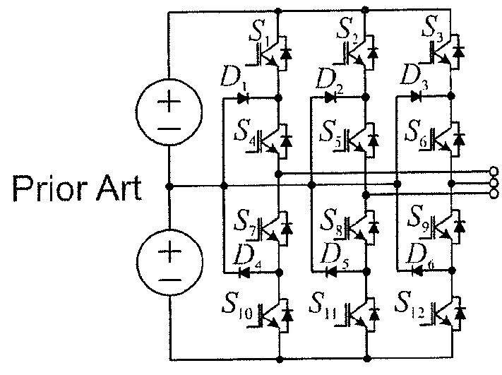
a three-phase current and voltage source technology, applied in the direction of electric variable regulation, process and machine control, instruments, etc., can solve the problems of increasing the overall switching loss of the npc topology, the inability of the two-level voltage source inverter to always be suitable for applications, and the relatively high conduction loss of the inner slower switching switch ssub>4 /sub>to ssub>9 /sub>,

Active Publication Date: 2016-05-17
ABB (SCHWEIZ) AG
View PDF9 Cites 6 Cited by
  • Summary
  • Abstract
  • Description
  • Claims
  • Application Information

AI Technical Summary

Benefits of technology

[0038]When the produced output three-phase current is sinusoidal and in phase with the output / load voltage, the positive route and the negative route together carry a large majority of the supplied power. The positive and negative currents can both be produced by using one switching device, and, therefore, the disclosed inverter topology can be implemented by using only two fast switching devices with a high current rating. As the middle route carries only a small portion of the total power, the current shaping part of the middle route can be implemented with switching devices having lower current ratings. The semiconductors distributing the shaped currents can be low-frequency components.
[0039]The disclosed method and inverter topology can be implemented cost-efficiently by using only a few high current, high switching frequency switching devices. The disclosed method and inverter topology can also provide a higher power density, as the core size of the output inductors can be reduced by increasing the switching frequency. The inverter can be connected to the three-phase grid directly, without a transformer. This further reduces the overall size and cost of the system. Also, there can be no high frequency ground leakage currents flowing through the DC voltage source terminals and the grounded frame.

Problems solved by technology

Because of high switching losses on the semiconductors, the known two-level voltage source inverter topology cannot always be suitable for applications with high switching frequency.
A drawback of this topology is that the inner slower switching switches S4 to S9 have relatively high conduction losses.
In comparison with the topology of FIG. 2a, all semiconductors have to be rated capable of fast switching, and, thus, overall switching losses can become higher than those of the NPC topology.
The WBG semiconductors can be, however, more expensive than pure Silicon (Si) devices.
The topology of FIG. 2c would have six expensive WBG switches, which can be seen as a drawback to the topology.
The semiconductor losses can be high, and a current through a DC link inductor L1 circulates all the time which can lead to high power losses in the DC link inductor L1.
Total Harmonic Distortion (THD) of the output current can be very poor.

Method used


Image

  • Method and apparatus for producing three-phase current
  • Method and apparatus for producing three-phase current
  • Method and apparatus for producing three-phase current

Examples


Embodiment Construction

[0032]Exemplary embodiments of the present disclosure provide a method and an apparatus for implementing the method so as to alleviate the above disadvantages.

[0033]An exemplary embodiment of the present disclosure discloses a method and an apparatus implementing the method, which can be used to convert DC voltage to a three-phase AC voltage / current. The disclosed method and inverter can be used, for example, for providing a sinusoidal, in-phase three-phase output current to a three-phase power network.

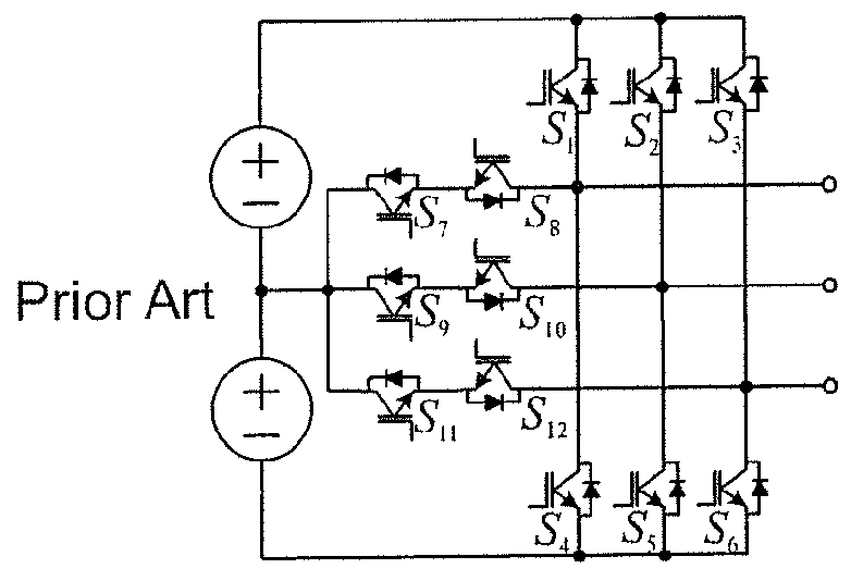
[0034]The exemplary method implements a multi-level-current concept for forming three-phase currents. In order to form three sinusoidal output phase currents, an inverter implementing the disclosed method can comprise three routes for current: a positive, a negative and a middle route.

[0035]A positive current through the positive route can follow the highest phase of a sinusoidal three-phase reference at a given time, a negative current through the negative route can follow the lowest...


PUM


Abstract

Exemplary embodiments are directed to methods and systems for producing a three-phase current to a three-phase output. Switching converters are used to generate a positive current, a negative current, and an intermediate current. The system is configured such that the produced positive current follows a path of a highest phase of a sinusoidal three-phase signal at a given time, the produced negative current follows a path of a lowest phase of the three-phase signal at the given time, and the produced intermediate current follows a path of a phase of the three-phase signal between the highest and the lowest phase at the given time. The produced currents are switched to each phase conductor of the three-phase output in sequence so that phase currents of the three-phase current are formed in the output conductors.

Description

RELATED APPLICATION[0001]This application claims priority under 35 U.S.C. §119 to European Patent Application No. 13156384.3 filed in Europe on Feb. 22, 2013, the content of which is hereby incorporated by reference in its entirety.FIELD[0002]The present disclosure relates to three-phase voltage source inverters, and more particularly to converting a DC voltage into three-phase currents by using a multi-level-current concept.BACKGROUND INFORMATION[0003]Plants generating renewable energy can be considered key components in the next generation of power systems, such as smart grids and microgrids. As discussed in the document by B. Burger and D. Kranzer titled “Extreme High Efficiency PV-Power Converter,” in Proc. EPE09, September 2009, these plants can also provide an alternate power source to known energy sources, such as oil, coal and natural gas.[0004]A known characteristic for a renewable energy generating process is that an inverter is used in the process as an interface transfor...

Claims


Application Information

Patent Timeline
Patent Type & Authority Patents(United States)
IPC IPC(8): H02M7/06H02M3/335H02M7/49H03B1/00H02M7/493H02M7/487
CPCH02M7/49H02M3/335H02M7/493H03B1/00H02M7/487H02M7/4837H02M1/0043
Inventor HO, NGAI-MANESCOBAR, GERARDOCANALES, FRANCISCO
Owner ABB (SCHWEIZ) AG
Why Eureka
Try Eureka