
Pressure Control Strategies to Provide Uniform Treatment Streams in the Manufacture of Microelectronic Devices

a technology of microelectronic devices and treatment streams, applied in the direction of cleaning processes and utensils, cleaning process and utensils, chemistry apparatus and processes, etc., can solve the problems of inability to achieve chamber matching in practice, process performance and results may still be less uniform than might be desired, and the process performance and results may not be uniform enough to achieve the effect of being uniform, accurate control of process performance, and changing process performan

Active Publication Date: 2019-09-26
TEL EPION
View PDF0 Cites 4 Cited by
  • Summary
  • Abstract
  • Description
  • Claims
  • Application Information

AI Technical Summary

Benefits of technology

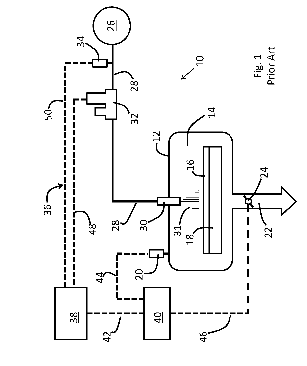
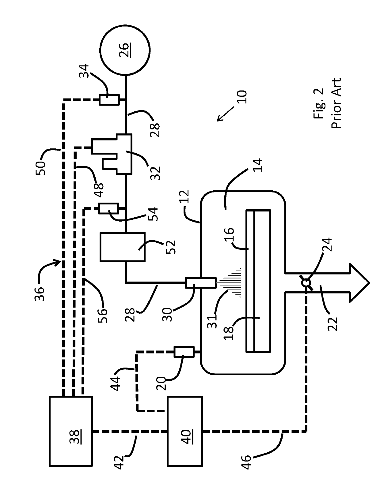
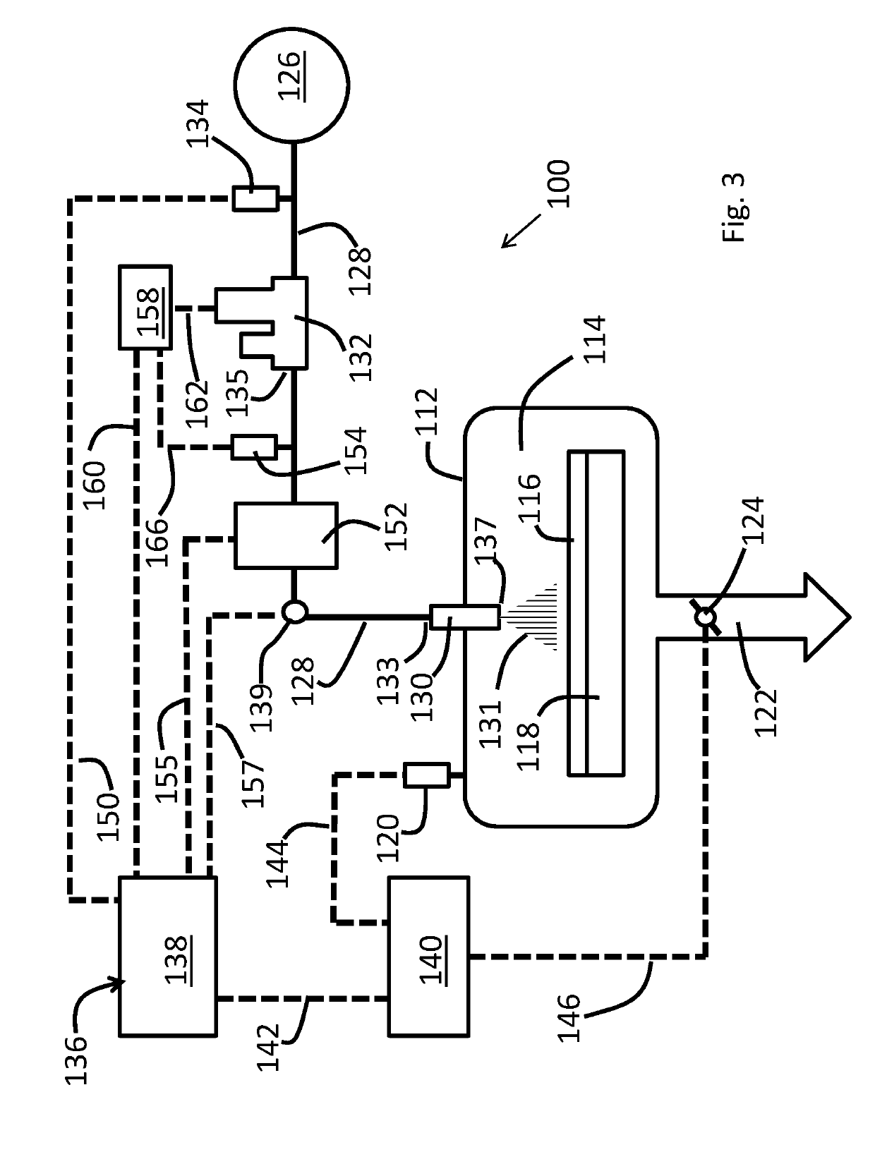
The present invention provides techniques for controlling the performance of treatments for microelectronic substrates by using pressure control strategies. These strategies read and control pressure features of a treatment system to ensure uniformity of process performance. These strategies also adjust mass flow rate responsive to pressure readings to hold the pressure of the pressurized fluid constant and improve chamber matching. Overall, the present invention optimizes and repeatably improves the performance of cryogenic cleaning treatment by controlling the pressure of the pressurized fluid and the pressure difference between the process chamber interior and the nozzle. The pressure control strategies also ease the process of chamber matching.

Problems solved by technology

In some modes of practice, the incoming feed desirably is maintained under pressure and temperature conditions that avoid the formation of liquid material in the supply line, as undue liquid formation in the feed could lead to increased contamination risk and or increased risk of damaging sensitive device features.
In other words, even though flow rate is accurately controlled, process performance and results may still be less uniform than might be desired as a function of time.
Chamber matching can be difficult to achieve in practice, as it can be challenging to machine different chambers and tools exactly the same.
Secondly, there also may be a variation in how a system is assembled, and this variation also can impact uniformity among tools and different process chambers.

Method used


Image

  • Pressure Control Strategies to Provide Uniform Treatment Streams in the Manufacture of Microelectronic Devices
  • Pressure Control Strategies to Provide Uniform Treatment Streams in the Manufacture of Microelectronic Devices
  • Pressure Control Strategies to Provide Uniform Treatment Streams in the Manufacture of Microelectronic Devices

Examples


Embodiment Construction

[0049]Methods for selectively removing objects from a microelectronic substrate are described in various embodiments. One skilled in the relevant art will recognize that the various embodiments may be practiced without one or more of the specific details, or with other replacement and / or additional methods, materials, or components. In other instances, well-known structures, materials, or operations are not shown or described in detail to avoid obscuring aspects of various embodiments of the disclosure. Similarly, for purposes of explanation, specific numbers, materials, and configurations are set forth to provide a thorough understanding of the systems and method. Nevertheless, the systems and methods may be practiced without specific details. Furthermore, it is understood that the various embodiments shown in the figures are illustrative representations and are not necessarily drawn to scale.

[0050]Reference throughout this specification to “one embodiment” or “an embodiment” means...


PUM


Abstract

The present invention provides techniques to more accurately control the process performance of treatments in which microelectronic substrates are treated by pressurized fluids that are sprayed onto the substrates in a vacuum process chamber. control strategies are used that adjust mass flow rate responsive to pressure readings in order to hold the pressure of a pressurized feed constant. In these embodiments, the mass flow rate will tend to vary in order to maintain pressure uniformity.

Description

PRIORITY[0001]This application claims priority to U.S. Provisional Patent Application No. 62 / 646,485, filed Mar. 22, 2018, titled “Systems and Method for Nano-Aerosol Gas and Pressure Control,” the entire disclosure of which is incorporated herein by reference for all purposes.FIELD OF THE INVENTION[0002]This disclosure relates to systems and methods for treating the surface of a microelectronic substrate in a vacuum pressure chamber with treatment streams(s), and in particular for removing objects from the microelectronic substrate using pressurized fluid material that is dispensed as one or more fluid streams through one or more nozzles into the chamber and at the substrate, wherein pressure control strategies are used to control pressures of the incoming, pressurized fluid material supplied to the nozzle(s) as well as the vacuum chamber pressure.BACKGROUND OF THE INVENTION[0003]Many processes used in the manufacturing of microelectronic devices involve positioning one or more mic...

Claims


Application Information

Patent Timeline
Patent Type & Authority Applications(United States)
IPC IPC(8): B08B3/02B08B3/10
CPCB08B2203/0229B08B2203/007B08B3/02H01L21/67051B08B3/10H01L21/02041H01L21/67017H01L21/67109
Inventor SIEFERING, KEVINHANZLIK, EDWARD
Owner TEL EPION
Learn More